СИСТЕМА УПРАВЛЕНИЯ ДВИГАТЕЛЯ
3.5L
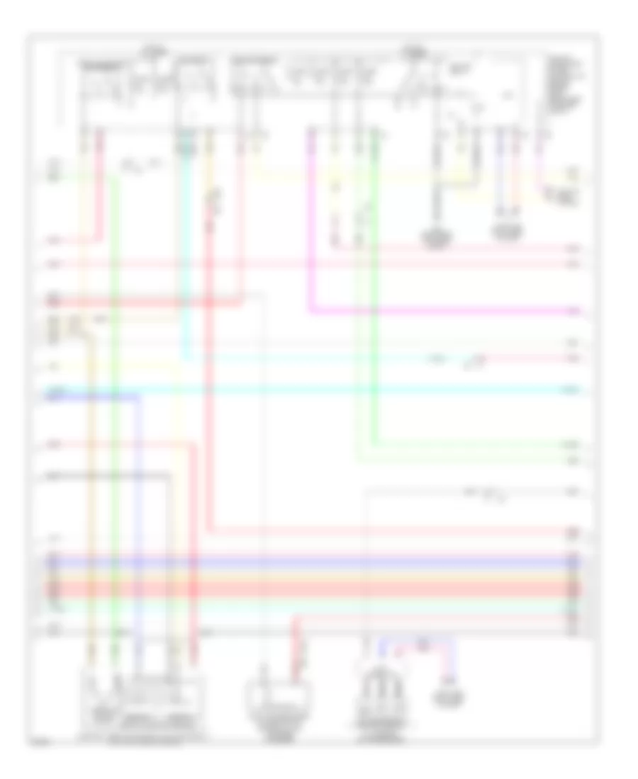
3.5L, Электросхема системы управления двигателя (1 из 4) для Infiniti EX35 2011

3.5L, Электросхема системы управления двигателя (1 из 4) для Infiniti EX35 2011 - Список элементов:
- (front of right cylinder bank)
- (right front of engine) f34
- (top of left cylinder bank) ignition coil 2 (w/ power transistor)
- (top of left cylinder bank) ignition coil 4 (w/ power transistor)
- (top of left cylinder bank) ignition coil 6 (w/ power transistor)
- (top of right cylinder bank) condenser
- (top of right cylinder bank) ignition coil 1 (w/ power transistor)
- (top of right cylinder bank) ignition coil 3 (w/ power transistor)
- (top of right cylinder bank) ignition coil 5 (w/ power transistor)
- Af+1
- Af-1
- Afh1
- Afh2
- Avcc phase 1
- Avcc phase 2
- Avcc pos
- Avcc tps
- Close
- Crankshaft position sensor (pos) (right rear of engine)
- Cvtc 1
- Cvtc 2
- E phase 1
- E phase 2
- Ecm (engine control module) (right end of dash)
- Electric throttle control actuator (bank 2) (top left side of engine)
- Evap
- Evtc 1
- Evtc 2
- Exhaust valve timing control magnet retarder (bank 1) (front of right cylinder bank)
- Exhaust valve timing control magnet retarder (bank 2) (front of left cylinder bank)
- F101
- F102
- Fpr
- Gnd
- Gnd a(tps)
- Gnd pos
- Gnda intpres
- Ign 1
- Ign 2
- Ign 3
- Ign 4
- Ign 5
- Ign 6
- Ignsw
- Intake valve timing control solenoid valve (bank 1)
- Intake valve timing control solenoid valve (bank 2) (front of left cylinder bank)
- M95 (right side of dash)
- Motor1 1
- Motor1 2
- Motor2 1
- Motor2 2
- Motrly1
- Nca
- O2hr1
- O2hr2
- Open
- Phase 1
- Phase 2
- Plug spark
- Pnk
- Pos
- Red
- Sensor 1
- Sensor 2
- Spark plug
- Ssoff
- Tan
- Throttle control motor
- Throttle position sensor
- Tps1 1
- Tps1 2
- Tps2 1
- Tps2 2
- Vmot1
- Vmot2
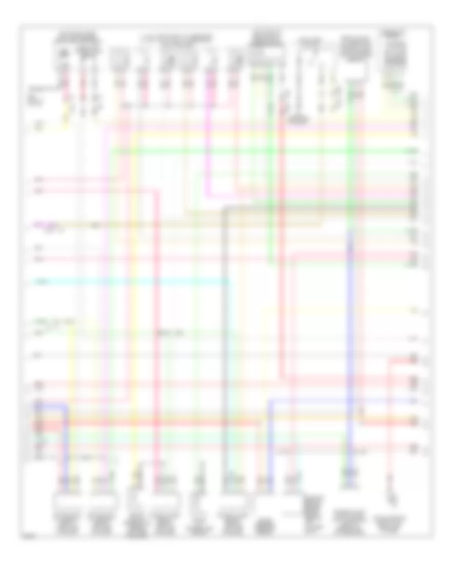
3.5L, Электросхема системы управления двигателя (2 из 4) для Infiniti EX35 2011
3.5L, Электросхема системы управления двигателя (2 из 4) для Infiniti EX35 2011 - Список элементов:
- A/t assembly (on transmission)
- Can h
- Can l
- Close
- Computer data lines system
- Cooling fans system
- Cpu
- E106
- E22 (right rear of engine compt)
- Ecm relay
- Electric throttle control actuator (bank 1) (top right side of engine)
- Evap canister purge volume control solenoid valve (top rear of engine)
- F1 e3
- F103
- Fuel pump relay
- Fuse 10a
- Fuse 15a
- Hot at all times
- Ignition relay
- Ipdm e/r (intelligent power distribution module engine room) (right rear of engine compt)
- Joint connector
- M116
- Nca
- Open
- Pnk
- Red
- Sensor 1
- Sensor 2
- St rly
- Tan
- Tcm (transmission control module)
- Throttle control motor
- Throttle control motor relay
- Throttle position sensor
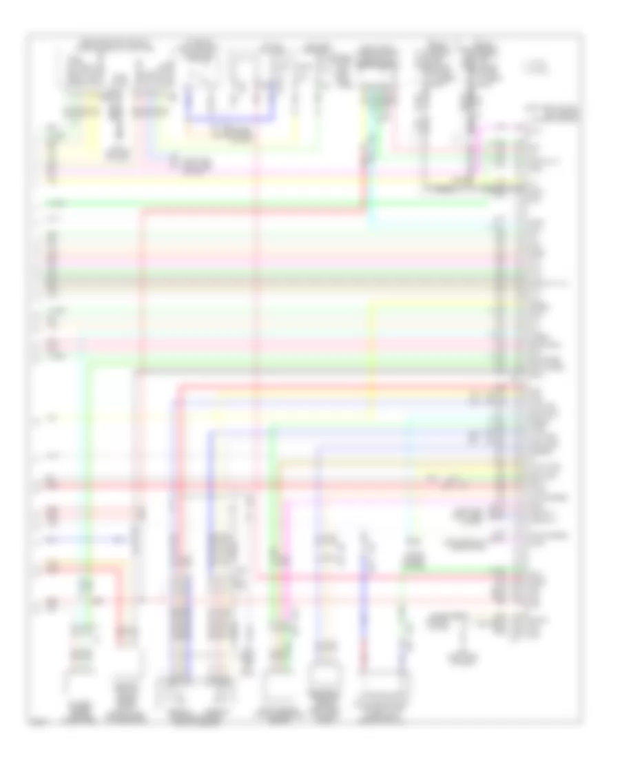
3.5L, Электросхема системы управления двигателя (3 из 4) для Infiniti EX35 2011
3.5L, Электросхема системы управления двигателя (3 из 4) для Infiniti EX35 2011 - Список элементов:
- (1, 3 & 5: top of right cylinder bank) (2, 4 & 6: top of left cylinder bank) fuel injectors
- (left front of engine compt) mass air flow sensor (bank 2)
- (rear of right cylinder bank) exhaust valve timing control position sensor (bank 1)
- (top of fuel tank) fuel level sensor unit & fuel pump (main)
- Air fuel ratio (a/f) sensor 1 (bank 1) (right side of engine)
- Air fuel ratio (a/f) sensor 1 (bank 2) (left side of engine)
- B24 (left "c" pillar)
- Camshaft position sensor (phase) (bank 2) (rear of left cylinder bank)
- Combination meter
- Comm amp lcd
- Comm amp mtr
- Comm lcd amp
- Comm mtr amp
- E104
- E106
- Engine coolant temperature sensor (left rear of engine)
- Engine oil temperature sensor
- Exhaust valve timing control position sensor (bank 2) (rear of left cylinder bank)
- F1 e3
- F103
- Fuel pump
- Fuel tank temperature sensor
- Heated oxygen sensor 2 (bank 1) (left side of engine)
- Heated oxygen sensor 2 (bank 2) (left side of engine)
- M116
- M170 m134
- M95 (right side of dash)
- Nca
- Pnk
- Power steering control unit (right side of dash)
- Power steering pressure sensor
- Red
- Snow mode switch
- Tacho eng
- Tan
3.5L, Электросхема системы управления двигателя (4 из 4) для Infiniti EX35 2011
3.5L, Электросхема системы управления двигателя (4 из 4) для Infiniti EX35 2011 - Список элементов:
- (behind center console) unified meter & a/c amplifier
- (on brake pedal bracket) stop lamp switch
- (or pnk)
- (or red)
- (right end of dash) ecm (engine control module)
- (right front of engine compt) mass air flow sensor (bank 1)
- Accelerator pedal position sensor
- Af+2
- Af-2
- Amp lcd
- Amp meter
- Aps1
- Aps2
- Ascdsw
- At snow sw
- Avcc aps1
- Avcc aps2
- Avcc ftprs
- Avcc pdpress
- B201
- Bat pwr
- Batt
- Battery current sensor (on battery)
- Bnc sw
- Brake
- Camshaft position sensor (phase) (bank 1) (rear of right cylinder bank)
- Can h
- Can l
- Cdcv
- Computer data lines system
- Cruise control system
- Cursen
- E103
- E106
- Evap canister vent control valve (under right rear of vehicle)
- Evap control system pressure sensor
- F102
- F103
- F103 m116
- F201 f9
- Ftprs
- Fuse 10a
- Fuse block (j/b) (left kick panel)
- Gnd
- Gnd a
- Gnd a(aps1)
- Gnd a(aps2)
- Gnd phase 2
- Gnd pspres
- Gnda ascd
- Gnda cursen
- Gnda o2 tw to
- Gnda pdpress
- Gnda qa ta
- Hot at all times
- Hot in on or start
- Ign pwr
- Inj 1
- Inj 2
- Inj 3
- Inj 4
- Inj 5
- Inj 6
- Kline
- Knk1
- Knk2
- Knock sensor (bank 1) (top center of right cylinder bank)
- Knock sensor (bank 2) (top center of left cylinder bank)
- Lcd amp
- M107
- M11 (left end of dash)
- M116
- M117
- M66
- M67
- M95 (right side of dash)
- Meter amp
- Neut h
- O2sr1
- O2sr2
- Pdpress
- Pnk
- Pspres
- Qa1+
- Qa2+
- Red
- Refrigerant pressure sensor (right front of engine compt)
- Sens gnd
- Sensor 1
- Sensor 2
- Shield
- Ta+2
- Ta1
- Tacho
- Tan
- To1
- Vbr
- Vehcan h1
- Vehcan l1
- W/ icc
- W/o icc