СИСТЕМА УПРАВЛЕНИЯ ДВИГАТЕЛЯ
3.5L
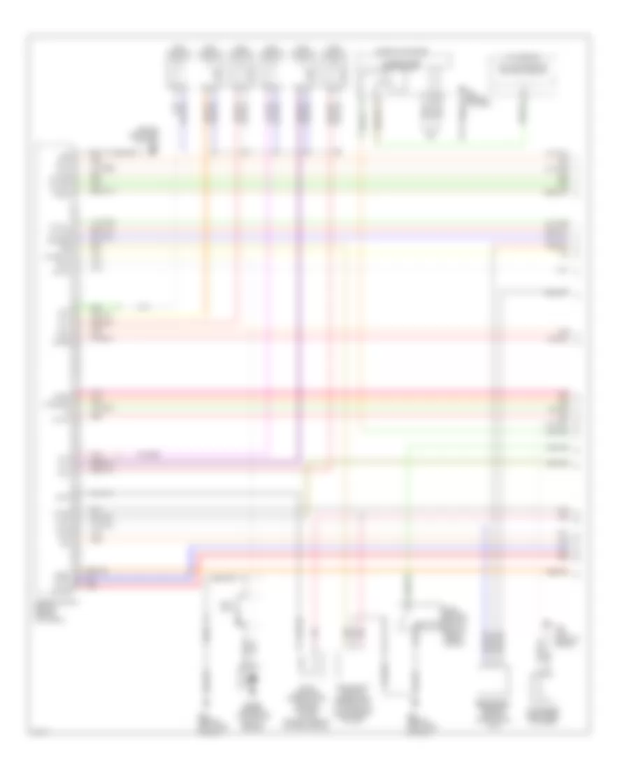
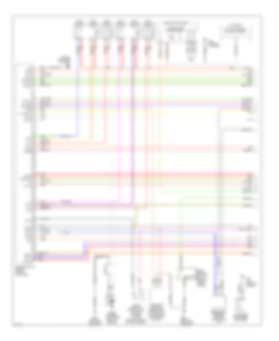
3.5L, Электросхема системы управления двигателя, Купе (1 из 4) для Infiniti G35 2005
 https://portal-diagnostov.com/license.html
Automotive Electricians Portal FZCO
Automotive Electricians Portal FZCO
https://portal-diagnostov.com/license.html
https://portal-diagnostov.com/license.html
Automotive Electricians Portal FZCO
Automotive Electricians Portal FZCO
3.5L, Электросхема системы управления двигателя, Купе (1 из 4) для Infiniti G35 2005 - Список элементов:
- (behind right side of dash)
- A/t assembly
- Af-h1
- Af-h2
- Af-ip1
- Af-un1
- Af-vm1
- Af-vm2
- Avcc
- Avcc2
- C-ivc (l)
- C-ivc (r)
- Combination meter
- Condenser (right rear of engine)
- Crankshaft position sensor (pos) (on front of oil pan, below crankshaft pulley)
- Engine control module (behind glove box)
- Evap
- Evap canister purge volume control solenoid valve (on right side of intake manifold)
- F23 (top front of engine)
- Ftrps
- Fuel injector
- Gnd
- Inj 1
- Inj 2
- Inj 3
- Inj 4
- Inj 5
- Inj 6
- Knk1
- Knock sensor (top center front of engine)
- M30 (behind cluster)
- M66
- M66 (behind right side of dash)
- Motor1
- Motor2
- Nca
- Neutral
- O2hrl
- O2hrr
- O2srl
- Park/ neutral position switch (rear of trans- mission)
- Phase lh
- Phase rh
- Pnk
- Pos
- Ps pres
- Qa+
- Red
- Refrigerant pressure sensor (on a/c liquid tank)
- Tcm (transmission control module)
- Tps1
- Unified meter control unit
- V mot
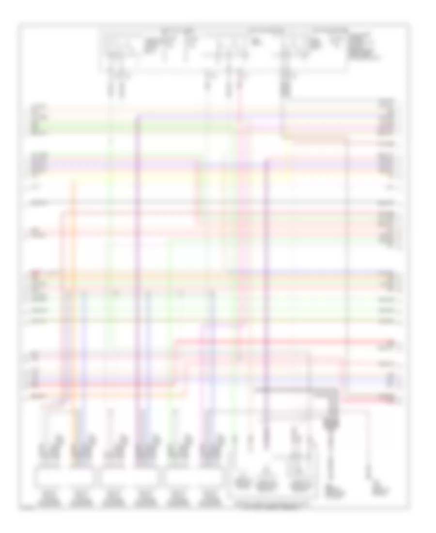
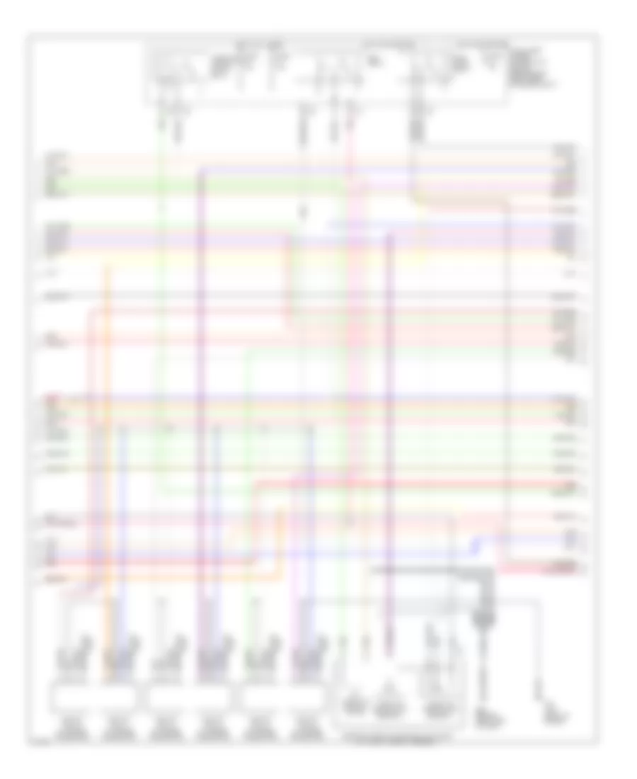
3.5L, Электросхема системы управления двигателя, Купе (2 из 4) для Infiniti G35 2005
 https://portal-diagnostov.com/license.html
Automotive Electricians Portal FZCO
Automotive Electricians Portal FZCO
https://portal-diagnostov.com/license.html
https://portal-diagnostov.com/license.html
Automotive Electricians Portal FZCO
Automotive Electricians Portal FZCO3.5L, Электросхема системы управления двигателя, Купе (2 из 4) для Infiniti G35 2005 - Список элементов:
- Ecm relay
- Electric throttle control actuator (on throttle body assembly)
- F23 (top front of engine)
- F31
- Fuel pump relay
- Fuse 15a
- Hot at all times
- Hot in on or start
- Ignition coil 1 (w/ power transistor)
- Ignition coil 2 (w/ power transistor)
- Ignition coil 3 (w/ power transistor)
- Ignition coil 4 (w/ power transistor)
- Ignition coil 5 (w/ power transistor)
- Ignition coil 6 (w/ power transistor)
- Intelligent power distribution module (engine room) (right rear of engine compt)
- M66 (behind right side of dash)
- Nca
- Nca nca
- Plug spark
- Pnk
- Red
- Spark plug
- Throttle control motor
- Throttle control motor relay
- Throttle position (tp) sensor 1
- Throttle position (tp) sensor 2
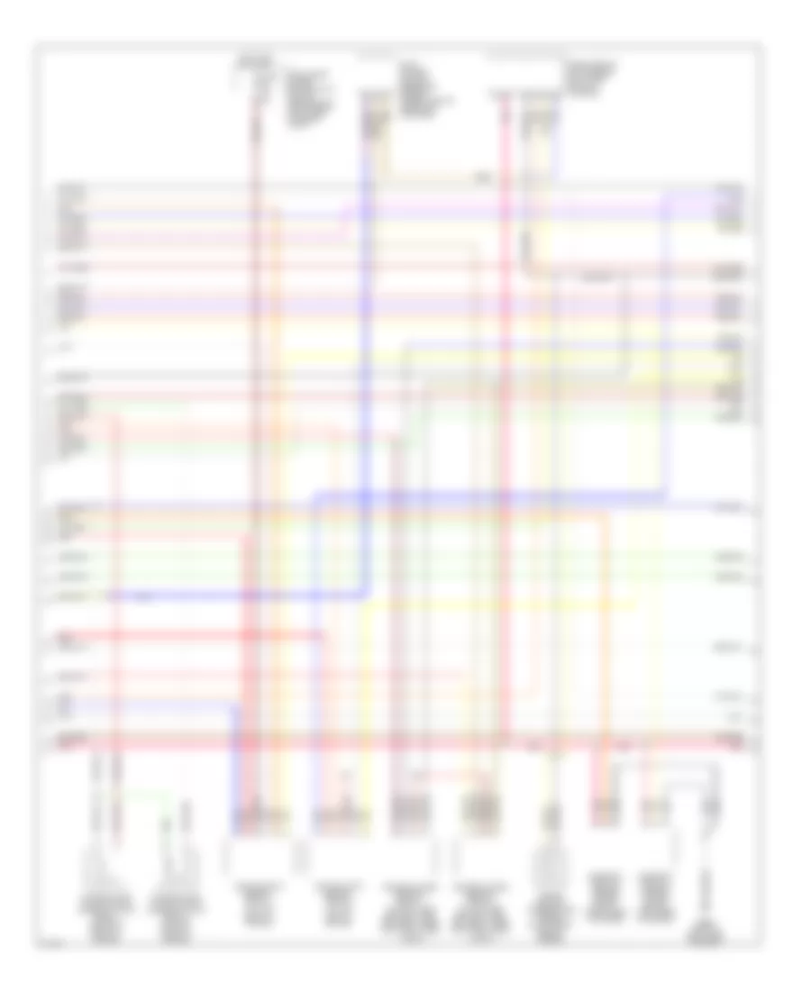
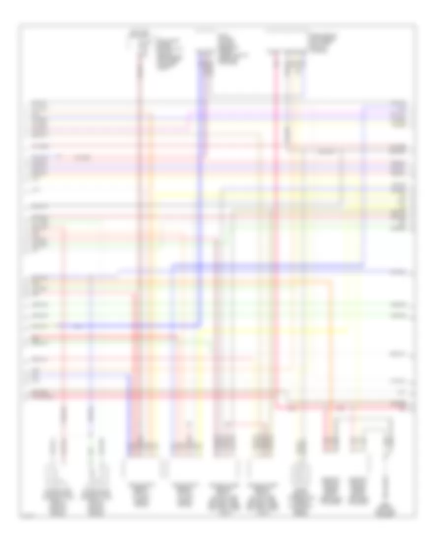
3.5L, Электросхема системы управления двигателя, Купе (3 из 4) для Infiniti G35 2005
 https://portal-diagnostov.com/license.html
Automotive Electricians Portal FZCO
Automotive Electricians Portal FZCO
https://portal-diagnostov.com/license.html
https://portal-diagnostov.com/license.html
Automotive Electricians Portal FZCO
Automotive Electricians Portal FZCO3.5L, Электросхема системы управления двигателя, Купе (3 из 4) для Infiniti G35 2005 - Список элементов:
- Air fuel ratio sensor 1 (bank 1) (at top right of engine)
- Air fuel ratio sensor 1 (bank 2) (at top left of engine)
- Camshaft position sensor (phase) (bank 1) (right rear of engine)
- Camshaft position sensor (phase) (bank 2) (left rear of engine)
- Engine coolant temperature sensor (on top right rear of engine)
- Evap control system pressure sensor (under vehicle, near evap canister)
- Fuse 15a
- Heated oxygen sensor 2 (bank 1) (on right side exhaust pipe, between three way catalysts 1 and 2)
- Heated oxygen sensor 2 (bank 2) (on left side exhaust pipe, between three way catalysts 1 and 2)
- Hot in on or start
- Intake valve timing control solenoid valve (bank 1) (on right front of engine)
- Intake valve timing control solenoid valve (bank 2) (on left front of engine)
- Intelligent power distribution module (engine room) (right rear of engine compt)
- M66 (behind right side of dash)
- Mass airflow (maf) sensor (on intake air duct housing)
- Pnk
- Red
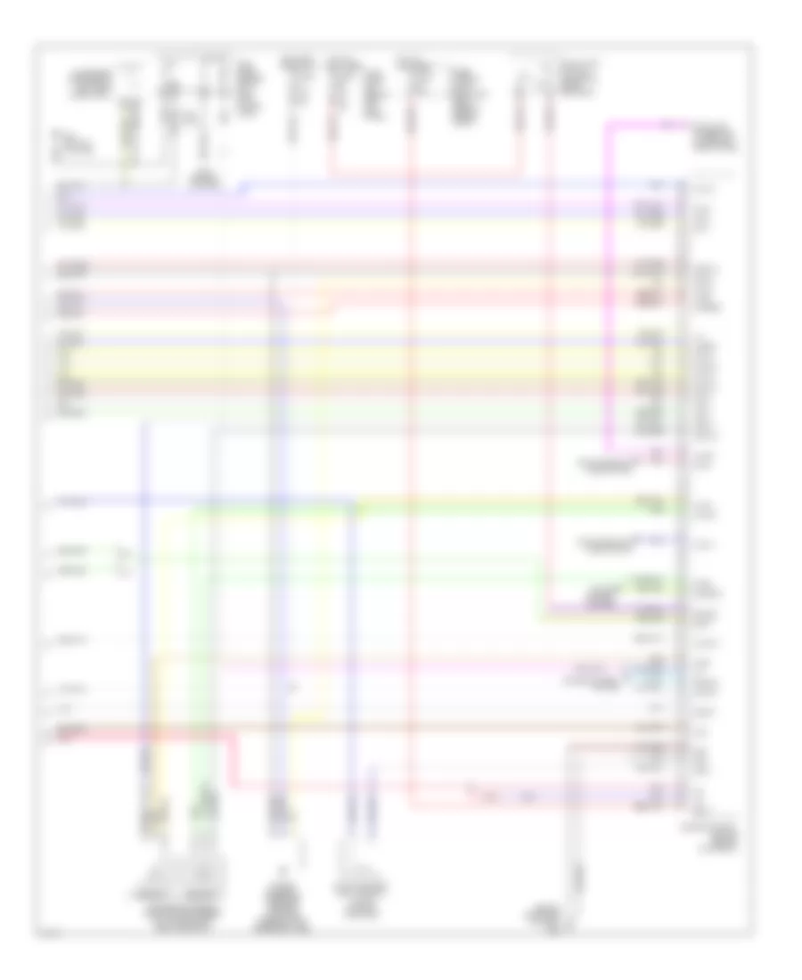
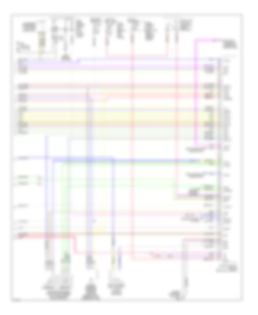
3.5L, Электросхема системы управления двигателя, Купе (4 из 4) для Infiniti G35 2005
 https://portal-diagnostov.com/license.html
Automotive Electricians Portal FZCO
Automotive Electricians Portal FZCO
https://portal-diagnostov.com/license.html
https://portal-diagnostov.com/license.html
Automotive Electricians Portal FZCO
Automotive Electricians Portal FZCO3.5L, Электросхема системы управления двигателя, Купе (4 из 4) для Infiniti G35 2005 - Список элементов:
- (behind right side of dash)
- 15a
- A/t
- Accelerator pedal position (app) sensor (on accelerator pedal bracket)
- Af-ia1
- Af-ia2
- Af-ip2
- Af-un2
- Aps1
- Aps2
- Ascdsw
- Avcc
- Avcc2
- B29 (on left c pillar)
- Batt
- Bncsw
- Brake
- Can l
- Can-h
- Cdcv
- Computer data lines system
- Condenser (forward of left rear wheelwell)
- Cruise control system
- Data link connector (lower left side of dash)
- E101
- Engine control module (behind glove box)
- Evap canister vent control valve (on evap canister)
- Fpr
- Fuel level sensor unit & fuel pump (in fuel tank)
- Fuse 10a
- Fuse 15a
- Fuse block (j/b) (behind left kick panel)
- Fuse, fusible link & relay box (right rear of engine compt)
- Gnd
- Gnd 02
- Gnd a
- Gnd a2
- Hot at all times
- Hot in on or start
- Ign 1
- Ign 2
- Ign 3
- Ign 4
- Ign 5
- Ign 6
- Ign sw
- Kline
- M/t
- M30 (behind cluster)
- M66
- Motrly
- Neut
- O2srr
- Pdpres
- Pnk
- Power steering pressure sensor (on power steering high pressure tube)
- Sensor 1
- Sensor 2
- Ssoff
- Stop lamp switch (on brake pedal bracket)
- Tps2
3.5L, Электросхема системы управления двигателя, седан (1 из 4) для Infiniti G35 2005
 https://portal-diagnostov.com/license.html
Automotive Electricians Portal FZCO
Automotive Electricians Portal FZCO
https://portal-diagnostov.com/license.html
https://portal-diagnostov.com/license.html
Automotive Electricians Portal FZCO
Automotive Electricians Portal FZCO3.5L, Электросхема системы управления двигателя, седан (1 из 4) для Infiniti G35 2005 - Список элементов:
- (behind right side of dash)
- A/t assembly
- Af-h1
- Af-h2
- Af-ip1
- Af-un1
- Af-vm1
- Af-vm2
- Avcc
- Avcc2
- C-ivc (l)
- C-ivc (r)
- Combination meter
- Condenser (right rear of engine)
- Crankshaft position sensor (pos) (on front of oil pan, below crankshaft pulley)
- Engine control module (behind glove box)
- Evap
- Evap canister purge volume control solenoid valve (on right side of intake manifold)
- F23 (top front of engine)
- Ftrps
- Fuel injector
- Gnd
- Inj 1
- Inj 2
- Inj 3
- Inj 4
- Inj 5
- Inj 6
- Knk1
- Knock sensor (top center front of engine)
- M30 (behind cluster)
- M66
- M66 (behind right side of dash)
- Motor1
- Motor2
- Nca
- Neutral
- O2hrl
- O2hrr
- O2srl
- Park/ neutral position switch (rear of trans- mission)
- Phase lh
- Phase rh
- Pnk
- Pos
- Ps pres
- Qa+
- Red
- Refrigerant pressure sensor (on a/c liquid tank)
- Tcm (transmission control module)
- Tps1
- Unified meter control unit
- V mot
3.5L, Электросхема системы управления двигателя, седан (2 из 4) для Infiniti G35 2005
 https://portal-diagnostov.com/license.html
Automotive Electricians Portal FZCO
Automotive Electricians Portal FZCO
https://portal-diagnostov.com/license.html
https://portal-diagnostov.com/license.html
Automotive Electricians Portal FZCO
Automotive Electricians Portal FZCO3.5L, Электросхема системы управления двигателя, седан (2 из 4) для Infiniti G35 2005 - Список элементов:
- Ecm relay
- Electric throttle control actuator (on throttle body assembly)
- F23 (top front of engine)
- F31
- Fuel pump relay
- Fuse 15a
- Hot at all times
- Hot in on or start
- Ignition coil 1 (w/ power transistor)
- Ignition coil 2 (w/ power transistor)
- Ignition coil 3 (w/ power transistor)
- Ignition coil 4 (w/ power transistor)
- Ignition coil 5 (w/ power transistor)
- Ignition coil 6 (w/ power transistor)
- Intelligent power distribution module (engine room) (right rear of engine compt)
- M66 (behind right side of dash)
- Nca
- Nca nca
- Plug spark
- Pnk
- Red
- Spark plug
- Throttle control motor
- Throttle control motor relay
- Throttle position (tp) sensor 1
- Throttle position (tp) sensor 2
3.5L, Электросхема системы управления двигателя, седан (3 из 4) для Infiniti G35 2005
 https://portal-diagnostov.com/license.html
Automotive Electricians Portal FZCO
Automotive Electricians Portal FZCO
https://portal-diagnostov.com/license.html
https://portal-diagnostov.com/license.html
Automotive Electricians Portal FZCO
Automotive Electricians Portal FZCO3.5L, Электросхема системы управления двигателя, седан (3 из 4) для Infiniti G35 2005 - Список элементов:
- Air fuel ratio sensor 1 (bank 1) (at right side of engine)
- Air fuel ratio sensor 1 (bank 2) (at left side of engine)
- Camshaft position sensor (phase) (bank 1) (right rear of engine)
- Camshaft position sensor (phase) (bank 2) (left rear of engine)
- Engine coolant temperature sensor (on top right rear of engine)
- Evap control system pressure sensor (under vehicle, near evap canister)
- Fuse 15a
- Heated oxygen sensor 2 (bank 1) (on right side exhaust pipe, between three way catalysts 1 and 2)
- Heated oxygen sensor 2 (bank 2) (on left side exhaust pipe, between three way catalysts 1 and 2)
- Hot in on or start
- Intake valve timing control solenoid valve (bank 1) (on right front of engine)
- Intake valve timing control solenoid valve (bank 2) (on left front of engine)
- Intelligent power distribution module (engine room) (right rear of engine compt)
- M66 (behind right side of dash)
- Mass airflow (maf) sensor (on intake air duct housing)
- Pnk
- Red
3.5L, Электросхема системы управления двигателя, седан (4 из 4) для Infiniti G35 2005
 https://portal-diagnostov.com/license.html
Automotive Electricians Portal FZCO
Automotive Electricians Portal FZCO
https://portal-diagnostov.com/license.html
https://portal-diagnostov.com/license.html
Automotive Electricians Portal FZCO
Automotive Electricians Portal FZCO3.5L, Электросхема системы управления двигателя, седан (4 из 4) для Infiniti G35 2005 - Список элементов:
- (behind right side of dash)
- 15a
- A/t
- Accelerator pedal position (app) sensor (on accelerator pedal bracket)
- Af-ia1
- Af-ia2
- Af-ip2
- Af-un2
- Aps1
- Aps2
- Ascdsw
- Avcc
- Avcc2
- B29 (on left c pillar)
- Batt
- Bncsw
- Brake
- Can l
- Can-h
- Cdcv
- Computer data lines system
- Condenser (forward of left rear wheelwell)
- Cruise control system
- Data link connector (lower left side of dash)
- E101
- Engine control module (behind glove box)
- Evap canister vent control valve (on evap canister)
- Fpr
- Fuel level sensor unit & fuel pump (in fuel tank)
- Fuse 10a
- Fuse 15a
- Fuse block (j/b) (behind left kick panel)
- Fuse, fusible link & relay box (right rear of engine compt)
- Gnd
- Gnd 02
- Gnd a
- Gnd a2
- Hot at all times
- Hot in on or start
- Ign 1
- Ign 2
- Ign 3
- Ign 4
- Ign 5
- Ign 6
- Ign sw
- Kline
- M/t
- M30 (behind cluster)
- M66
- Motrly
- Neut
- O2srr
- Pdpres
- Pnk
- Power steering pressure sensor (on power steering high pressure tube)
- Sensor 1
- Sensor 2
- Ssoff
- Stop lamp switch (on brake pedal bracket)
- Tps2

 Čeština
 Dansk
Dansk Deutsch
 Ελληνικά
 English
 English
 Español
 Suomi
Suomi Français
 Français
 עברית
עברית Hrvatski
 Magyar
 Italiano
 日本語
日本語 Nederlands
 Polski
 Português
 Português
 Română
 Русский
 Slovenčina
 Slovenščina
 Svenska
 Türkçe
 中文 (中国)
