СИСТЕМА УПРАВЛЕНИЯ ДВИГАТЕЛЯ
3.5L
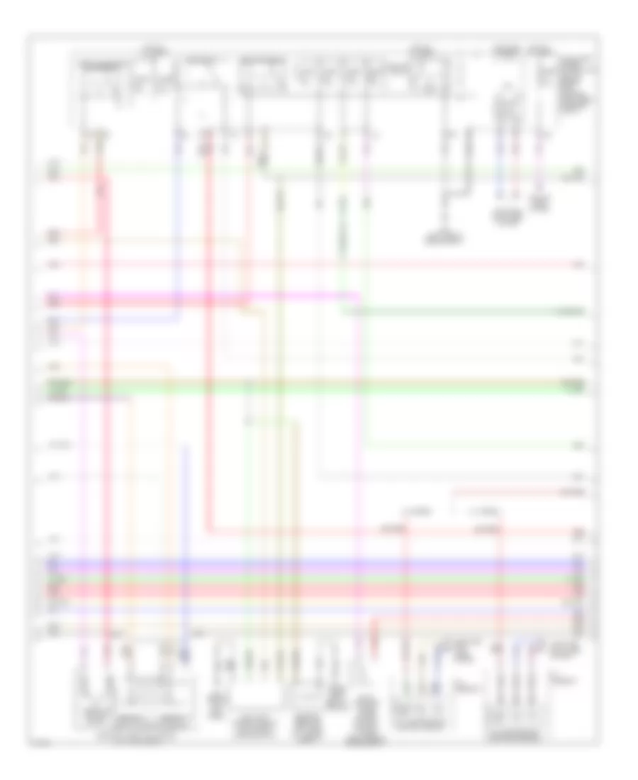
3.5L, Электросхема системы управления двигателя (1 из 4) для Infiniti M35 2010

3.5L, Электросхема системы управления двигателя (1 из 4) для Infiniti M35 2010 - Список элементов:
- (near left "c" pillar) condenser
- (top front of engine) f22
- Af+1
- Af-1
- Afh1
- Afh2
- Avcc tps b1
- Avcc1
- Avcc1 tpp
- Avcc2
- Avcc2 pos
- C evc1
- C evc2
- C ivc1
- Close
- Crankshaft position sensor (pos) (left front of engine)
- E phase 1
- E phase 2
- Ecm (engine control module) (behind right side of dash)
- Electric throttle control actuator (bank 2)
- Evap
- Exhaust valve timing control magnet retarder (bank 1)
- Exhaust valve timing control magnet retarder (bank 2)
- F105
- F106
- Fpcm
- Fpcmck
- Fpr
- Gnd
- Gnd pos
- Gnda tps
- Gnda tps b2
- Ign 1
- Ign 2
- Ign 3
- Ign 4
- Ign 5
- Ign 6
- Ignition coils (w/ power transistor) (coils 1, 3 & 5: top right of engine) (coils 2, 4 & 6: top left of engine)
- Ignsw
- Intake valve timing control solenoid valve (bank 1) (right front of engine)
- Intake valve timing control solenoid valve (bank 2) (left front of engine)
- Loop wire
- M70 (right end of dash)
- Motor1 b1
- Motor1 b2
- Motor2 b1
- Motor2 b2
- Motrly
- Nca
- O2hr1
- O2hr2
- Open
- Phase 1
- Phase 2
- Plug spark
- Pnk
- Pos
- Red
- Sensor 1
- Sensor 2
- Spark plug
- Ssoff
- Throttle control motor
- Throttle position sensor
- Tps1 b1
- Tps1 b2
- Tps2 b1
- Tps2 b2
- Vmot b1
- Vmot b2
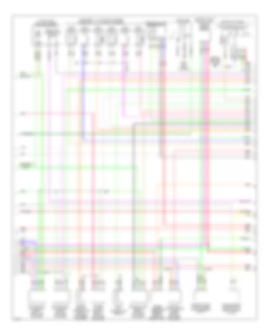
3.5L, Электросхема системы управления двигателя (2 из 4) для Infiniti M35 2010
3.5L, Электросхема системы управления двигателя (2 из 4) для Infiniti M35 2010 - Список элементов:
- (under right rear of vehicle)
- +ig
- A/t assembly
- Actuator (bank 1)
- B131
- B5 (behind left kick panel)
- Can- h
- Can- l
- Close
- Computer data lines system
- Cooling fans system
- Cpu
- Dropping resistor (left side of luggage compt)
- E43 (left side of engine compt)
- Ecm relay
- Electric throttle control
- Evap canister purge volume control solenoid valve (right side of engine compt)
- Fuel pump control module (left side of luggage compt)
- Fuel pump relay
- Fuse 10a
- Fuse 15a
- Fuse 20a
- Gnd(pwr)
- Gnd(sig)
- Hot at all times
- Hot in on or start
- Ignition relay
- Intelligent power distribution module engine room (ipdm e/r) (right rear of engine compt)
- Nca
- Open
- Pnk
- Red
- Sensor 1
- Sensor 2
- Start rly
- Tcm (transmission control module)
- Throttle control motor
- Throttle control motor relay
- Throttle position sensor
- W/ 5-speed
- W/ 7-speed
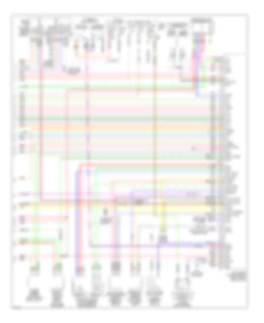
3.5L, Электросхема системы управления двигателя (3 из 4) для Infiniti M35 2010
3.5L, Электросхема системы управления двигателя (3 из 4) для Infiniti M35 2010 - Список элементов:
- (behind left end of dash) m16
- (in fuel tank) fuel level sensor unit & fuel pump
- (injectors 2, 4, 6: top left of engine) (injectors 1, 3, 5: top right of engine)
- Air fuel ratio (a/f) sensor 1 (bank 1) (right side of engine)
- Air fuel ratio (a/f) sensor 1 (bank 2) (left side of engine)
- Camshaft position sensor (phase) (bank 2) (left rear of engine)
- Combination meter
- Engine coolant temperature sensor (right rear of engine)
- Engine oil temperature sensor
- Exhaust valve timing control position sensor (bank 2)
- Exhaust valve timing control position sensor (bank1)
- Fuel injector
- Fuel pump
- Fuel tank temperature sensor
- Gnd
- Heated oxygen sensor 2 (bank 1) (left side of engine)
- Heated oxygen sensor 2 (bank 2) (left front of engine)
- Ign
- Ind
- M70 (right end of dash)
- Mass airflow (maf) sensor (bank2)
- Mil ind
- Nca
- Pnk
- Power steering control unit (behind center of dash)
- Power steering pressure sensor (front of engine compt)
- Red
- Snow mode switch
- Unified meter control unit (w/ dot matrix lcd)
3.5L, Электросхема системы управления двигателя (4 из 4) для Infiniti M35 2010
3.5L, Электросхема системы управления двигателя (4 из 4) для Infiniti M35 2010 - Список элементов:
- (on brake pedal bracket)
- (top center front of engine)
- 15a
- Accelerator pedal position sensor (on accelerator pedal bracket)
- Af+2
- Af-2
- Aps1
- Aps2
- Ascd brake switch (w/o icc) icc brake switch (w/ icc) (on brake pedal bracket)
- Ascdsw
- At-p
- Avcc aps2
- Avcc1 aps1
- Avcc2 ftprs
- Avcc2 pdpress
- Batt
- Battery current sensor (right side of engine compt)
- Bnc sw
- Brake
- Camshaft position sensor (phase) (bank 1) (right rear of engine)
- Can-h
- Can-l
- Cdcv
- Computer data lines system
- Console)
- Cruise control system
- Cursen
- E101
- E103
- Ecm (engine control module) (behind right side of dash)
- Evap canister vent control valve (under right rear of vehicle)
- Evap control system pressure sensor (under right rear of vehicle)
- F106
- Ftprs
- Fuse 10a
- Fuse 15a
- Fuse block (j/b)
- Gnd
- Gnd a
- Gnd phase 2
- Gnda
- Gnda aps1
- Gnda aps2
- Gnda ascdsw
- Gnda cursen
- Gnda ftprs
- Gnda knk
- Hot at all times
- Hot in on or start
- Icc brake hold relay
- Ign
- Inj 1
- Inj 2
- Inj 3
- Inj 4
- Inj 5
- Inj 6
- Kline
- Knk1
- Knk2
- Knock sensor (bank 1)
- Knock sensor (bank 2)
- M16 (behind left end of dash)
- M64
- M65
- M70 (right end of dash)
- Mass airflow (maf) sensor (bank 1)
- Nca
- Neut h
- O2sr1
- O2sr2
- Pdpress
- Pnk
- Pspres
- Qa1+
- Qa2+
- Red
- Refrigerant pressure sensor (right front of engine compt)
- Sens gnd
- Sensor 1
- Sensor 2
- Snow sw
- Starting/ charging system
- Stop lamp switch
- Ta+2
- Ta1
- Tacho
- To1
- Unified meter a/c amplifier (behind center
- Vbr