СИСТЕМА УПРАВЛЕНИЯ ДВИГАТЕЛЯ
2.0L
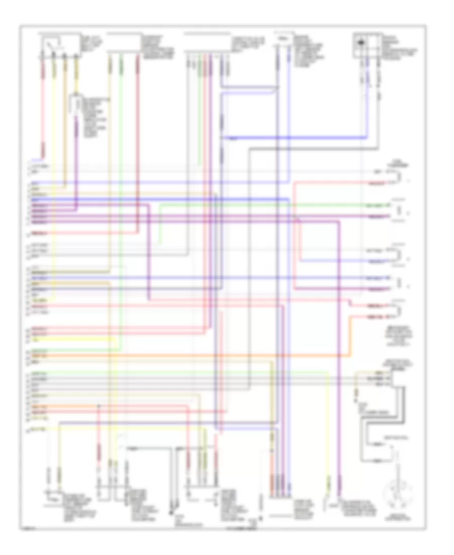
2.0L, Электросхема системы управления двигателя (1 из 2) для Volkswagen Golf GL 1998

2.0L, Электросхема системы управления двигателя (1 из 2) для Volkswagen Golf GL 1998 - Список элементов:
- (not used)
- (on engine block)
- 30b
- A/c clutch cut-off relay
- Battery
- Battery ground
- D/8
- Data link connector (center of dash)
- E/2
- Engine speed sensor (on cylinder block behind oil filter)
- Fuel pump
- Fuel pump relay
- Fuse 10a
- Fuse 20a
- Fuse 30a
- Fuse/ relay panel
- Fuse/relay panel
- G1/3
- G1/4
- G1/6
- G1/8
- G1/9
- G132
- G2/4
- G2/8
- G2/9
- Ignition
- Ignition (15)
- Instrument cluster
- Instrument cluster system
- Instrument cluster system (control module/ display unit)
- Junction block (above fuse/ relay panel)
- Junction connector
- Leak detection pump
- M/1
- M/2
- Malfunction indicator lamp
- Motronic engine control module (in engine compartment, on center of plenum)
- Nca
- Red
- Secondary air injection (air) pump motor (calif. only) (below intake manifold, near thermostat housing)
- Secondary air injection (air) pump relay (calif. only) (behind left headlight)
- T28/13
- T28/20
- Transmission control module
- U1/9
- U2/1
- U2/2
- Vehicle speed signal
- W/1
- Z/2
2.0L, Электросхема системы управления двигателя (2 из 2) для Volkswagen Golf GL 1998
2.0L, Электросхема системы управления двигателя (2 из 2) для Volkswagen Golf GL 1998 - Список элементов:
- Camshaft position sensor (in distributor housing, under sensor rotor)
- Engine coolant temperature (ect) sensor (at rear of cylinder head, in coolant flange)
- Evaporative emission (evap) canister purge regulator valve (right side of eng compt)
- Evaporative emission (evap) canister purge solenoid valve
- Fuel cut- off valve/ shut off relay
- Fuel injectors
- G132 (on cylinder head)
- G132 (on engine block)
- Heated oxygen sensor (ho2s) (in exhaust pipe, in front of 3-way converter)
- Heated oxygen sensor (ho2s) 2 (in exhaust pipe, in front of 3-way converter)
- Ignition coil
- Ignition coil power output stage
- Ignition distributor
- Intake air temperature (iat) sensor (front of intake manifold, near throttle body)
- Knock sensor (ks) (on engine block, near oil filter housing)
- Mass air flow (maf) sensor (in intake air duct)
- Nca
- Secondary air injection (air) solenoid valve (calif only)
- Throttle valve control module (at throttle body)