СИСТЕМА УПРАВЛЕНИЯ ДВИГАТЕЛЯ
2.3L
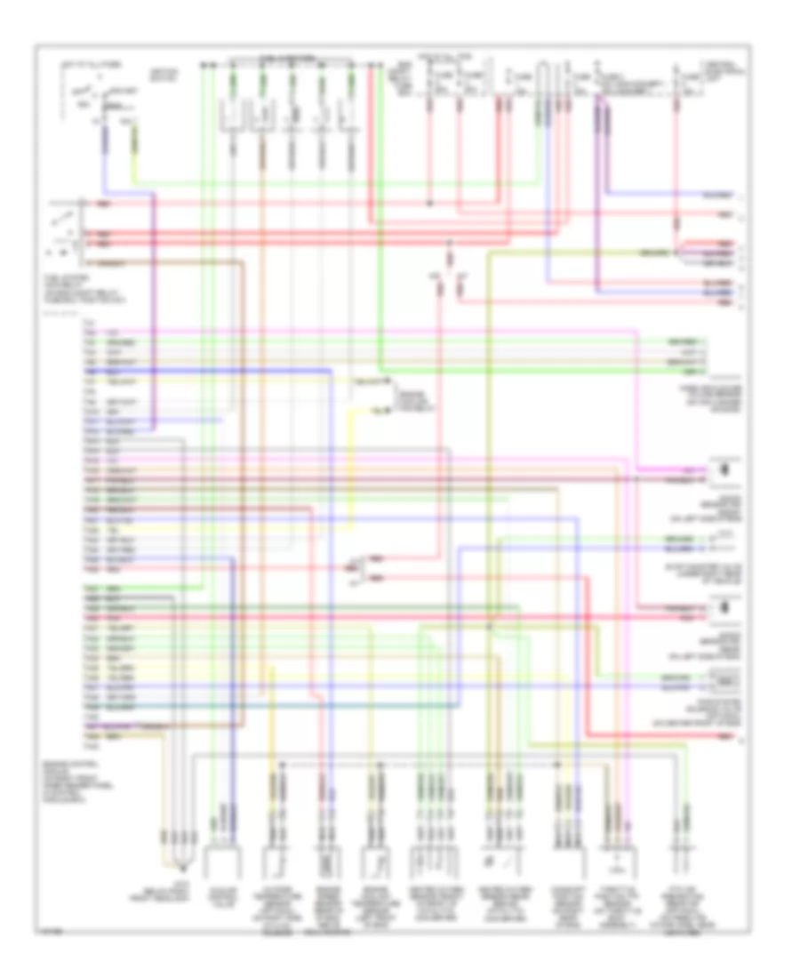
2.3L турбо, Электросхема системы управления двигателя (1 из 2) для Volvo S70 GLT 1998
2.3L турбо, Электросхема системы управления двигателя (1 из 2) для Volvo S70 GLT 1998 - Список элементов:
- (non-convert.) (convert.)
- (rear) (on left side of eng)
- 15a
- A/t
- A10
- A11
- A12
- A13
- A14
- A15
- A16
- A17
- A18
- A19
- A20
- A21
- A22
- A23
- A24
- A25
- A26
- A27
- A28
- A29
- A30
- A31
- A32
- A33
- A34
- A35
- A36
- A37
- A38
- A39
- A40
- A41
- A42
- A43
- Acc
- Camshaft position sensor (on right rear of eng)
- Central electrical unit
- Eng compt. relay/ fuse box
- Engine control module (on right front inner fender panel, in control module box)
- Engine coolant temperature sensor (left front of eng)
- Engine cooling fan relay
- Engine speed sensor (rear of of eng, above bellhousing)
- Evap canister valve (under right rear of vehicle)
- Fuel injectors
- Fuel system main relay (on eng compt relay/ fuse box, position no1)
- Fuse 10a
- Fuse 3 20a 15a
- Fuse 50a
- Fuse 60a
- G107 (below right front headlamp)
- Heated oxygen sensor (front) (in front of catalytic converter)
- Heated oxygen sensor (rear) (behind catalytic converter)
- Hot at all times
- Hot at all tims
- Idle air control valve
- Ignition switch
- Knock sensor (ks)
- Knock sensor (ks) (front) (on left side of eng)
- M/t
- Mass air flow/air volume sensor (on air cleaner housing)
- Nca
- Off
- Outside temperature sensor (optional) (on right side of hvac housing)
- Pair system solenoid valve (optional) (on center front of eng)
- Pnk
- Ptc air preheating resistor (optional) (on fresh air intake hose, near air filter)
- Red
- Run
- Start
- Throttle position (tp) sensor (on throttle body assembly)
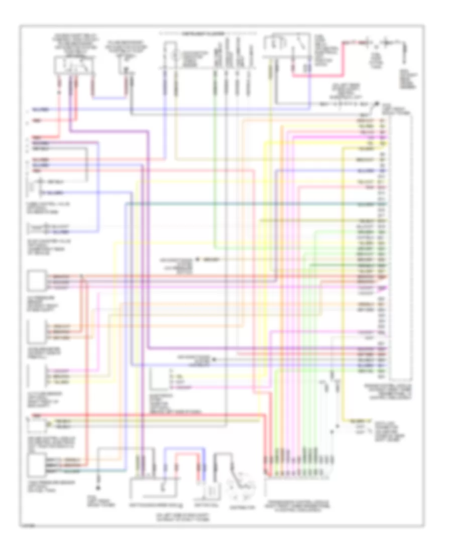
2.3L турбо, Электросхема системы управления двигателя (2 из 2) для Volvo S70 GLT 1998
2.3L турбо, Электросхема системы управления двигателя (2 из 2) для Volvo S70 GLT 1998 - Список элементов:
- (on eng compt relay/ fuse box, position no1) pulse secondary air injection system pump relay (optional)
- (on left rear of eng compt) central electrical unit
- (on left side of eng compt, on front of strut tower)
- (optional)
- A/c pressure sensor (on right front of eng compt)
- A/t
- A10
- A11
- A18
- A26
- Accelerometer (on right side of firewall)
- Air conditioning system (a/c pressure switch)
- Air conditioning system (a/c relay)
- Altitude sensor (optional) (right front of eng compt)
- B10
- B11
- B12
- B13
- B14
- B15
- B16
- B17
- B18
- B19
- B20
- B21
- B22
- B23
- B24
- B25
- B26
- B27
- B28
- B29
- B30
- B31
- B32
- B33
- B34
- B35
- B36
- B37
- B38
- B39
- B40
- B41
- B42
- B43
- Cruise control module (on central electrical unit, position nos101 & 102)
- Data link connector (on center console, near shift lever)
- Distributor
- Electronic start inhibitor (optional) (behind left side of dash)
- Eng temp gauge input
- Engine control module (on right front inner fender panel, in control module box)
- Evap canister valve (optional) (under right rear of vehicle)
- Fuel pump (in fuel tank)
- Fuel pump relay (on central electrical unit, position no103)
- G102 (left front shock tower)
- G303 (on right rear cross- member)
- Igniti0n coil
- Ignition discharge module
- Input trip computer
- Instrument cluster
- Malfunction indicator "check engine"
- Nca
- Pnk
- Pulse secondary air injection system pump relay pump
- Red
- Tach input
- Tank pressure sensor (optional) (on fuel tank)
- Transmission control module (right front inner fender panel, in control module box)
- Turbo control valve (optional) (on rear of eng)
- Vehicle speed output
2.4L
2.4L турбо, Электросхема системы управления двигателя (1 из 2) для Volvo S70 GLT 1998
2.4L турбо, Электросхема системы управления двигателя (1 из 2) для Volvo S70 GLT 1998 - Список элементов:
- (non-convert.) (convert.)
- (rear) (on left side of eng)
- 15a
- A/t
- A10
- A11
- A12
- A13
- A14
- A15
- A16
- A17
- A18
- A19
- A20
- A21
- A22
- A23
- A24
- A25
- A26
- A27
- A28
- A29
- A30
- A31
- A32
- A33
- A34
- A35
- A36
- A37
- A38
- A39
- A40
- A41
- A42
- A43
- Acc
- Camshaft position sensor (on right rear of eng)
- Central electrical unit
- Eng compt. relay/ fuse box
- Engine control module (on right front inner fender panel, in control module box)
- Engine coolant temperature sensor (left front of eng)
- Engine cooling fan relay
- Engine speed sensor (rear of of eng, above bellhousing)
- Evap canister valve (under right rear of vehicle)
- Fuel injectors
- Fuel system main relay (on eng compt relay/ fuse box, position no1)
- Fuse 10a
- Fuse 3 20a 15a
- Fuse 50a
- Fuse 60a
- G107 (below right front headlamp)
- Heated oxygen sensor (front) (in front of catalytic converter)
- Heated oxygen sensor (rear) (behind catalytic converter)
- Hot at all times
- Hot at all tims
- Idle air control valve
- Ignition switch
- Knock sensor (ks)
- Knock sensor (ks) (front) (on left side of eng)
- M/t
- Mass air flow/air volume sensor (on air cleaner housing)
- Nca
- Off
- Outside temperature sensor (optional) (on right side of hvac housing)
- Pair system solenoid valve (optional) (on center front of eng)
- Pnk
- Ptc air preheating resistor (optional) (on fresh air intake hose, near air filter)
- Red
- Run
- Start
- Throttle position (tp) sensor (on throttle body assembly)
2.4L турбо, Электросхема системы управления двигателя (2 из 2) для Volvo S70 GLT 1998
2.4L турбо, Электросхема системы управления двигателя (2 из 2) для Volvo S70 GLT 1998 - Список элементов:
- (on eng compt relay/ fuse box, position no1) pulse secondary air injection system pump relay (optional)
- (on left rear of eng compt) central electrical unit
- (on left side of eng compt, on front of strut tower)
- (optional)
- A/c pressure sensor (on right front of eng compt)
- A/t
- A10
- A11
- A18
- A26
- Accelerometer (on right side of firewall)
- Air conditioning system (a/c pressure switch)
- Air conditioning system (a/c relay)
- Altitude sensor (optional) (right front of eng compt)
- B10
- B11
- B12
- B13
- B14
- B15
- B16
- B17
- B18
- B19
- B20
- B21
- B22
- B23
- B24
- B25
- B26
- B27
- B28
- B29
- B30
- B31
- B32
- B33
- B34
- B35
- B36
- B37
- B38
- B39
- B40
- B41
- B42
- B43
- Cruise control module (on central electrical unit, position nos101 & 102)
- Data link connector (on center console, near shift lever)
- Distributor
- Electronic start inhibitor (optional) (behind left side of dash)
- Eng temp gauge input
- Engine control module (on right front inner fender panel, in control module box)
- Evap canister valve (optional) (under right rear of vehicle)
- Fuel pump (in fuel tank)
- Fuel pump relay (on central electrical unit, position no103)
- G102 (left front shock tower)
- G303 (on right rear cross- member)
- Igniti0n coil
- Ignition discharge module
- Input trip computer
- Instrument cluster
- Malfunction indicator "check engine"
- Nca
- Pnk
- Pulse secondary air injection system pump relay pump
- Red
- Tach input
- Tank pressure sensor (optional) (on fuel tank)
- Transmission control module (right front inner fender panel, in control module box)
- Turbo control valve (optional) (on rear of eng)
- Vehicle speed output
2.4L, Электросхема системы управления двигателя (1 из 2) для Volvo S70 GLT 1998
2.4L, Электросхема системы управления двигателя (1 из 2) для Volvo S70 GLT 1998 - Список элементов:
- (non-convert.) (convert.)
- (rear) (on left side of eng)
- 15a
- A/t
- A10
- A11
- A12
- A13
- A14
- A15
- A16
- A17
- A18
- A19
- A20
- A21
- A22
- A23
- A24
- A25
- A26
- A27
- A28
- A29
- A30
- A31
- A32
- A33
- A34
- A35
- A36
- A37
- A38
- A39
- A40
- A41
- A42
- A43
- Acc
- Camshaft position sensor (on right rear of eng)
- Central electrical unit
- Eng compt. relay/ fuse box
- Engine control module (on right front inner fender panel, in control module box)
- Engine coolant temperature sensor (left front of eng)
- Engine cooling fan relay
- Engine speed sensor (rear of of eng, above bellhousing)
- Evap canister valve (under right rear of vehicle)
- Fuel injectors
- Fuel system main relay (on eng compt relay/ fuse box, position no1)
- Fuse 10a
- Fuse 3 20a 15a
- Fuse 50a
- Fuse 60a
- G107 (below right front headlamp)
- Heated oxygen sensor (front) (in front of catalytic converter)
- Heated oxygen sensor (rear) (behind catalytic converter)
- Hot at all times
- Hot at all tims
- Idle air control valve
- Ignition switch
- Knock sensor (ks)
- Knock sensor (ks) (front) (on left side of eng)
- M/t
- Mass air flow/air volume sensor (on air cleaner housing)
- Nca
- Off
- Outside temperature sensor (optional) (on right side of hvac housing)
- Pair system solenoid valve (optional) (on center front of eng)
- Pnk
- Ptc air preheating resistor (optional) (on fresh air intake hose, near air filter)
- Red
- Run
- Start
- Throttle position (tp) sensor (on throttle body assembly)
2.4L, Электросхема системы управления двигателя (2 из 2) для Volvo S70 GLT 1998
2.4L, Электросхема системы управления двигателя (2 из 2) для Volvo S70 GLT 1998 - Список элементов:
- (on eng compt relay/ fuse box, position no1) pulse secondary air injection system pump relay (optional)
- (on left rear of eng compt) central electrical unit
- (on left side of eng compt, on front of strut tower)
- (optional)
- A/c pressure sensor (on right front of eng compt)
- A/t
- A10
- A11
- A18
- A26
- Accelerometer (on right side of firewall)
- Air conditioning system (a/c pressure switch)
- Air conditioning system (a/c relay)
- Altitude sensor (optional) (right front of eng compt)
- B10
- B11
- B12
- B13
- B14
- B15
- B16
- B17
- B18
- B19
- B20
- B21
- B22
- B23
- B24
- B25
- B26
- B27
- B28
- B29
- B30
- B31
- B32
- B33
- B34
- B35
- B36
- B37
- B38
- B39
- B40
- B41
- B42
- B43
- Cruise control module (on central electrical unit, position nos101 & 102)
- Data link connector (on center console, near shift lever)
- Distributor
- Electronic start inhibitor (optional) (behind left side of dash)
- Eng temp gauge input
- Engine control module (on right front inner fender panel, in control module box)
- Evap canister valve (optional) (under right rear of vehicle)
- Fuel pump (in fuel tank)
- Fuel pump relay (on central electrical unit, position no103)
- G102 (left front shock tower)
- G303 (on right rear cross- member)
- Igniti0n coil
- Ignition discharge module
- Input trip computer
- Instrument cluster
- Malfunction indicator "check engine"
- Nca
- Pnk
- Pulse secondary air injection system pump relay pump
- Red
- Tach input
- Tank pressure sensor (optional) (on fuel tank)
- Transmission control module (right front inner fender panel, in control module box)
- Turbo control valve (optional) (on rear of eng)
- Vehicle speed output

 Dansk
Dansk Deutsch
 Ελληνικά
 English
 English
 Español
 Suomi
Suomi Français
 Français
 עברית
עברית Hrvatski
 Magyar
 Italiano
 日本語
日本語 한국어
한국어 Nederlands
 Polski
 Português
 Português
 Română
 Русский
 Slovenčina
 Slovenščina
 Svenska
 Türkçe
 中文 (中国)