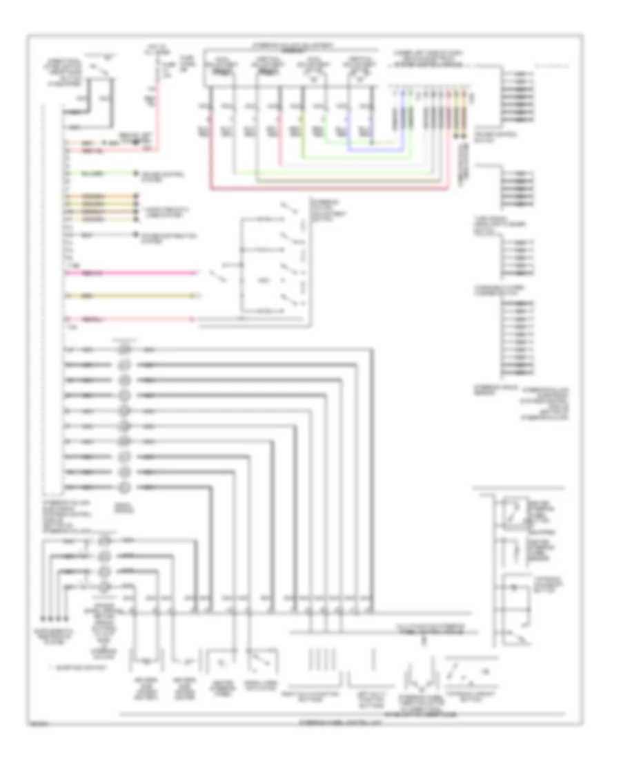
СИСТЕМА УСИЛИТЕЛЯ РУЛЯ
Электросхема усилителя руля для Audi A6 3.2 2011
Электросхема усилителя руля для Audi A6 3.2 2011 - Список элементов:
- (behind left kick panel)
- (under left side of dash) vehicle electrical system control module
- 13a
- Air bag spiral spring/ return spring slip ring (w/ slip ring) (in steering column)
- Axial adjustment motor
- Axial adjustment sensor
- Computer data lines system
- Cruise control switch
- Cruise control system
- Directional stabilization assistance button (if equipped)
- Driver's side air bag igniter
- Driver's side air bag igniter 2
- Fuse 10a
- Fuse panel sb
- G44
- Heated steering wheel
- Heated steering wheel button (if equipped)
- Heated steering wheel sensor
- Hot at all times
- Left multi- function buttons
- Multi-function steering wheel control module
- Nca
- Power distribution system
- Right multi-function buttons
- Shorting contact
- Signal horn activation
- Spiral spring
- Steering angle sensor
- Steering column adjustment assembly
- Steering column adjustment switch
- Steering column electronic systems control module (bottom of steering column)
- Steering wheel control unit
- Steering wheel vibration motor (w/ directional stabilization assistance)
- T12
- T16b
- T32c
- T4g
- Tiptronic downshift button
- Tiptronic upshift button
- Turn signal/ headlamp flasher switch
- Vertical adjustment motor
- Vertical adjustment sensor
- Windshield wiper/ washer switch
 English