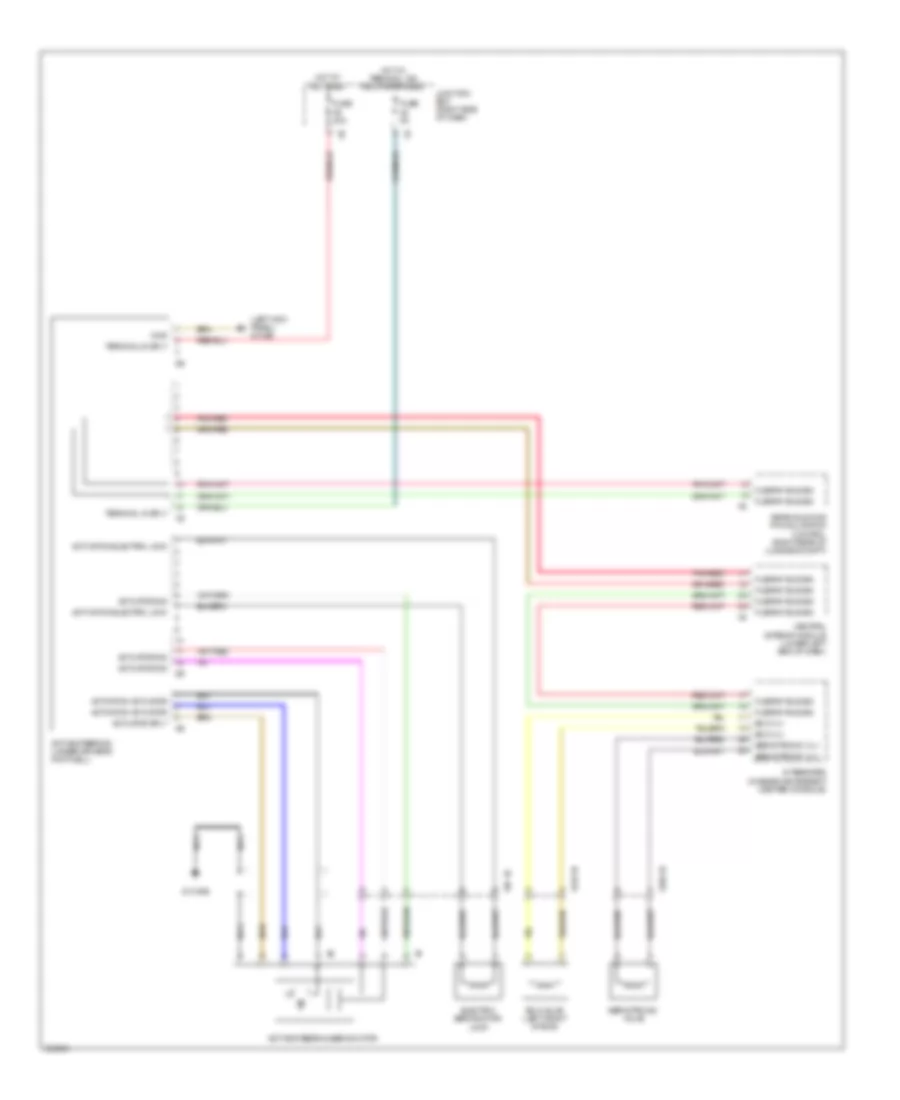
СИСТЕМА УСИЛИТЕЛЯ РУЛЯ
Электросхема усилителя руля для BMW 740Li 2011
Электросхема усилителя руля для BMW 740Li 2011 - Список элементов:
- (left kick panel) z10 5b
- Activation actuator
- Activation electric lock
- Active steering (under driver's footwell)
- Active steering servomotor
- Actuator sig
- Actuator sply
- Central gateway module (lower left end of dash)
- Eco valve (left front of eng)
- Eco vlv
- Electric servomotor lock
- Flexray bus sig
- Fuse 40a
- Fuse 5a
- Gnd
- Hot at all times
- Hot w/ terminal 15n relay energized
- Integrated chassis management (center console)
- Junction box (right side of dash)
- Nca
- Pnk/red
- Rear axle king pin inclination control (right rear of luggage compt)
- Servotronic valve
- Servotronic vlv
- Terminal 15 sply
- Terminal 30 sply
- X219 1b
- X335 1b
- X87 1b
- Z10 50b
 English