СИСТЕМА УСИЛИТЕЛЯ РУЛЯ
Электросхема усилителя руля для Buick Roadmaster Limited 1996
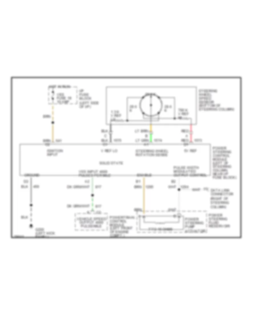
Электросхема усилителя руля для Buick Roadmaster Limited 1996 - Список элементов:
- (left side of i/p)
- (right of steering column)
- 1.3 k v ref lo
- 29.6 k
- 5v ref
- 7 to 15 ohms
- 790 k v ref hi
- Data link connector
- Enable
- G200 (left kick panel)
- Ground
- Hot in run
- I/p fuse block
- Ignition input
- Power steering control module (left of steering column, near i/p fuse block)
- Power steering fluid reservoir
- Power steering pump actuator
- Powertrain control module (left front of engine compt.)
- Pulse width modulated output control
- Red
- Red d1
- Solid state
- Steering wheel rotation sense
- Steering wheel speed sensor (bottom of steering column)
- V ref lo
- Vehicle speed output 4000 pulse/mile
- Ves fuse 18 10 amp
- Vss input 4000 pulses per mile
 Русский