СИСТЕМА УСИЛИТЕЛЯ РУЛЯ
Электросхема усилителя руля для MINI Cooper 2006
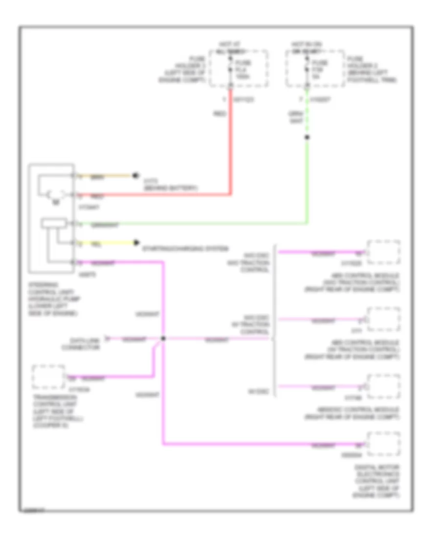
Электросхема усилителя руля для MINI Cooper 2006 - Список элементов:
- Abs control module (w/ traction control) (right rear of engine compt)
- Abs control module (w/o traction control) (right rear of engine compt)
- Abs/dsc control module (right rear of engine compt)
- Data link connector
- Digital motor electronics control unit (left side of engine compt)
- Fuse f39 5a
- Fuse fl4 100a
- Fuse holder 2 (behind left footwell trim)
- Fuse holder 3 (left side of engine compt)
- Hot at all times
- Hot in on or start
- Red
- Starting/charging system
- Steering control unit/ hydraulic pump (lower left side of engine)
- Transmission control unit (left side of left footwell) (cooper s)
- W/ dsc
- W/o dsc w/ traction control
- W/o dsc w/o traction control
- X01123
- X10207
- X11
- X11525
- X11634
- X13441
- X173 (behind battery)
- X1746
- X60004
- X6975
 Čeština
 Dansk
Dansk Deutsch
 Ελληνικά
 English
 English
 Español
 Suomi
Suomi Français
 Français
 עברית
עברית Hrvatski
 Magyar
 Italiano
 日本語
日本語 한국어
한국어 Polski
 Português
 Português
 Română
 Русский
 Slovenčina
 Slovenščina
 Svenska
 Türkçe
 中文 (中国)
 Nederlands