СИСТЕМА УСИЛИТЕЛЯ РУЛЯ
Электросхема усилителя руля для Mitsubishi Lancer Evolution MR 2013
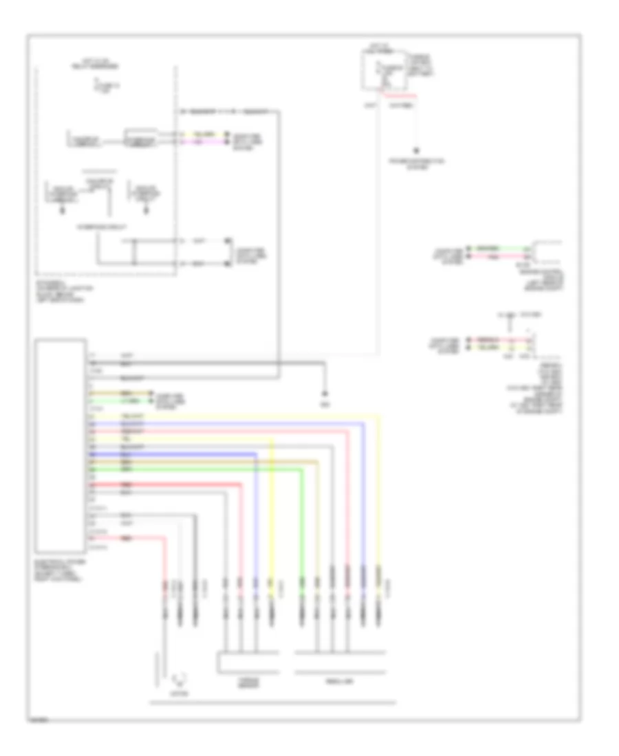
Электросхема усилителя руля для Mitsubishi Lancer Evolution MR 2013 - Список элементов:
- A-03
- A-51
- Abs-ecu (w/o asc) asc-ecu (w/ asc) (w/o asc: right rear corner of engine compt) (w/ asc: right rear of engine compt)
- Analog interface circuit
- B-109
- C-141
- C-141-1
- C-141-2
- C-141-3
- C-141-4
- C-141-5
- C-141-6
- C-141-7
- C140
- Can drive circuit
- Computer data lines system
- Electrical power steering ecu (except turbo: right kick panel)
- Engine control module (left rear of engine compt)
- Etacs-ecu (on rear of junction block, behind left end of dash)
- Fuse 12 7.5a
- Fusible link 80a
- Fusible link box (next to battery)
- G22
- Hot at all times
- Hot w/ ig1 relay energized
- Interface circuit
- Motor
- Nca
- Pnk
- Power distribution system
- Red
- Resolver
- Torque sensor
- W/o asc w/ asc
 Русский