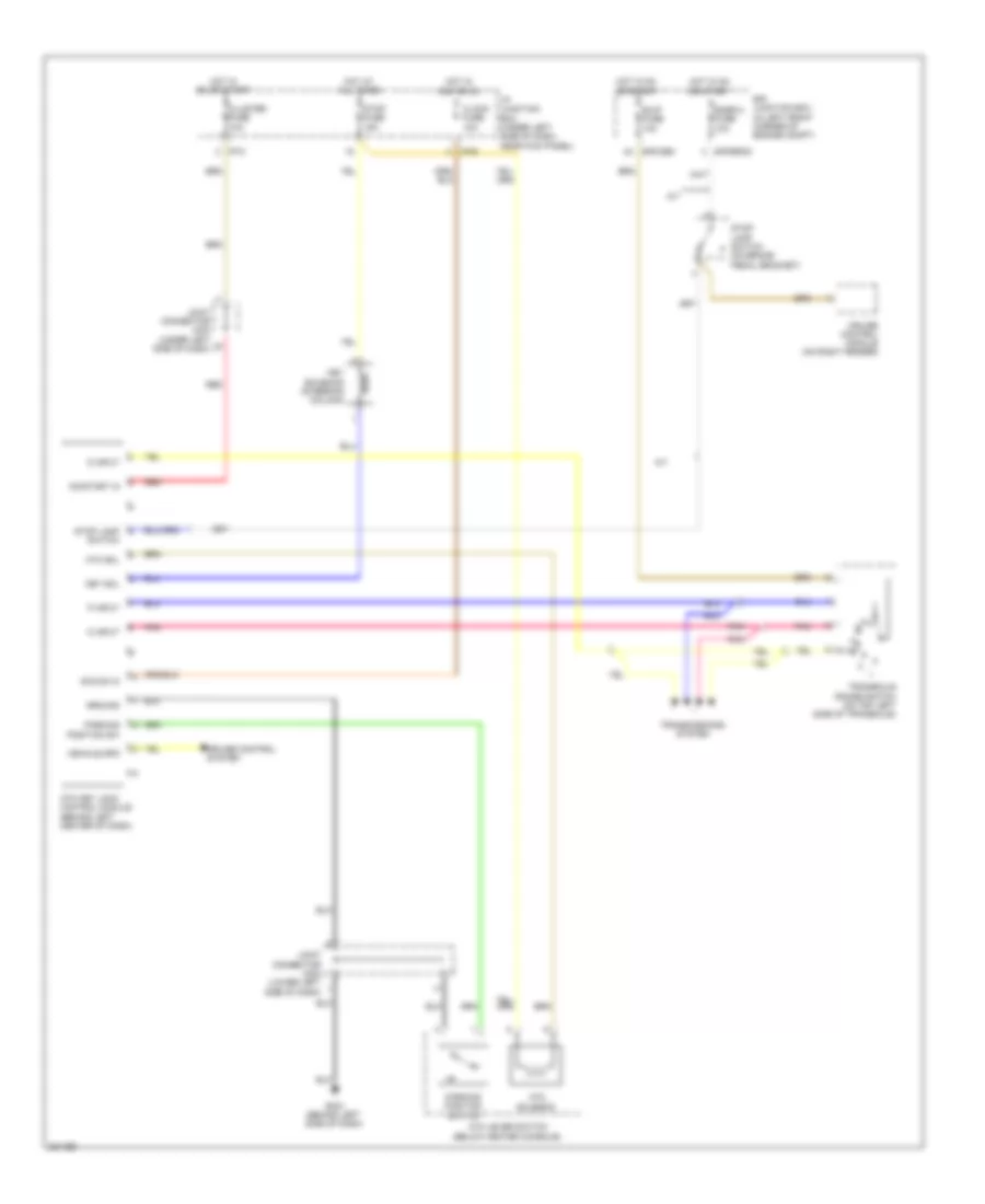
SHIFT INTERLOCK
Shift Interlock Wiring Diagram for Hyundai Elantra GLS 2010
List of elements for Shift Interlock Wiring Diagram for Hyundai Elantra GLS 2010:
- A/t
- Acc/on in
- Atm key lock control module (behind left center of dash)
- Atm lever switch (below center console)
- Atm sol
- Atm solenoid
- B/up fuse 10a
- Clock fuse 10a
- Cluster fuse 10a
- Cruise control module (on right fender)
- Cruise control system
- D input
- E/r junction box (in left front corner of engine compt)
- E/r-cbg
- E/r-erom
- Gm21 (behind left side of dash)
- Ground
- Hot at all times
- Hot in acc or on
- Hot in on or start
- I/p junction box (under left side of dash, near kick panel)
- I/p-b
- I/p-c
- Joint connector jm03 (under left side of dash)
- Joint connector jm04 (lower left side of dash)
- Key sol
- Key solenoid (steering column)
- N input
- On/start in
- P input
- Parking position sw
- Parking position switch
- Pnk
- Red
- Snsr 2 fuse 10a
- Stop fuse 15a
- Stop lamp switch
- Stop lamp switch (on brake pedal bracket)
- Transaxle range switch (on top left side of transaxle)
- Transmissions system
- Vehicle spd
 Čeština
 Dansk
Dansk Deutsch
 Ελληνικά
 English
 Español
 Suomi
Suomi Français
 Français
 עברית
עברית Hrvatski
 Magyar
 Italiano
 日本語
日本語 한국어
한국어 Nederlands
 Polski
 Português
 Português
 Română
 Русский
 Slovenčina
 Slovenščina
 Svenska
 Türkçe
 中文 (中国)
 English