
 Čeština
 Dansk
Dansk Deutsch
 Ελληνικά
 English
 Español
 Suomi
Suomi Français
 Français
 עברית
עברית Hrvatski
 Magyar
 Italiano
 日本語
日本語 한국어
한국어 Nederlands
 Polski
 Português
 Português
 Română
 Русский
 Slovenčina
 Slovenščina
 Svenska
 Türkçe
 中文 (中国)

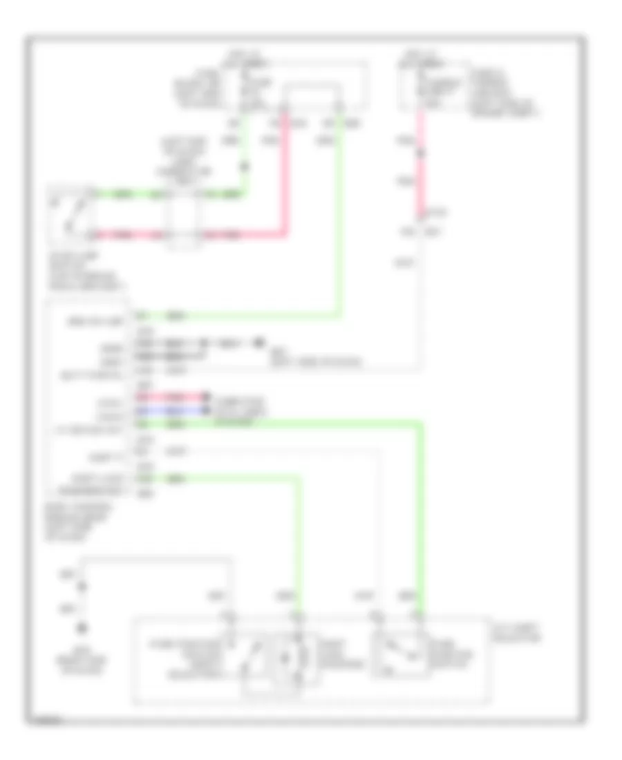
SHIFT INTERLOCK
Shift Interlock Wiring Diagram for Infiniti JX35 2013
List of elements for Shift Interlock Wiring Diagram for Infiniti JX35 2013:

STARTING/CHARGINGSUPPLEMENTAL RESTRAINTSTRUNK, TAILGATE, FUEL DOORTRANSMISSIONWARNING SYSTEMSWIPER/WASHERAIR CONDITIONINGANTI-LOCK BRAKESCOOLING FANCOMPUTER DATA LINESANTI-THEFTCRUISE CONTROLBODY CONTROL MODULESELECTRONIC POWER STEERINGDEFOGGERSEXTERIOR LIGHTSGROUND DISTRIBUTIONHEADLIGHTSENGINE PERFORMANCEINSTRUMENT CLUSTERHORNINTERIOR LIGHTSMEMORY SYSTEMSPOWER DISTRIBUTIONPASSIVE RESTRAINTSPOWER MIRRORSPOWER SEATSPOWER WINDOWSPOWER DOOR LOCKSNAVIGATIONPOWER TOP/SUNROOFSHIFT INTERLOCKRADIO