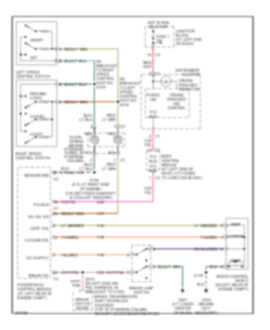
CRUISE CONTROL
Cruise Control Wiring Diagram for Chrysler Concorde LXi 2004
List of elements for Cruise Control Wiring Diagram for Chrysler Concorde LXi 2004:
- (2.7l:at right side of engine) (3.5l:between camshaft & coolant sensors)
- (behind steering wheel in steering column)
- (in breakout to left speed control switch) s218
- (in breakout to right speed control switch) s219
- Body control module (at left end of dash, attached to junction block)
- Brake lamp switch
- Brake sw
- Brake switch sense
- Brake transmission shift interlock solenoid (top of steering column, on shift lever mounting stud)
- Cancel
- Clock- spring
- Coast
- Cruise engaged ind control
- Cruise engaged indicator
- D25
- Dump
- Fuse 1 10a
- Fused ign
- G104 (behind left headlight)
- G201 (at lower center of dash)
- Hot in run or start
- Instrument cluster
- Junction block (at left end of dash)
- K29
- Left speed control switch
- Nca
- On/off
- Pci bus
- Powertrain control module (at left rear of engine compt)
- Resume/ accel
- Right speed control switch
- S/c sw sig
- S104
- S119
- S215 (in left side ins pnl harness, in breakout to c103)
- Sensor gnd
- Set
- Speed control servo (in left rear of engine compt)
- Tan/red
- V32
- V35
- V36
- V37
- Vacuum
- Vacuum sol
- Vent
- Vent sol
 Čeština
 Dansk
Dansk Deutsch
 Ελληνικά
 English
 Español
 Suomi
Suomi Français
 Français
 עברית
עברית Hrvatski
 Magyar
 Italiano
 日本語
日本語 한국어
한국어 Nederlands
 Polski
 Português
 Português
 Română
 Русский
 Slovenčina
 Slovenščina
 Svenska
 Türkçe
 中文 (中国)
 English