AIR CONDITIONING
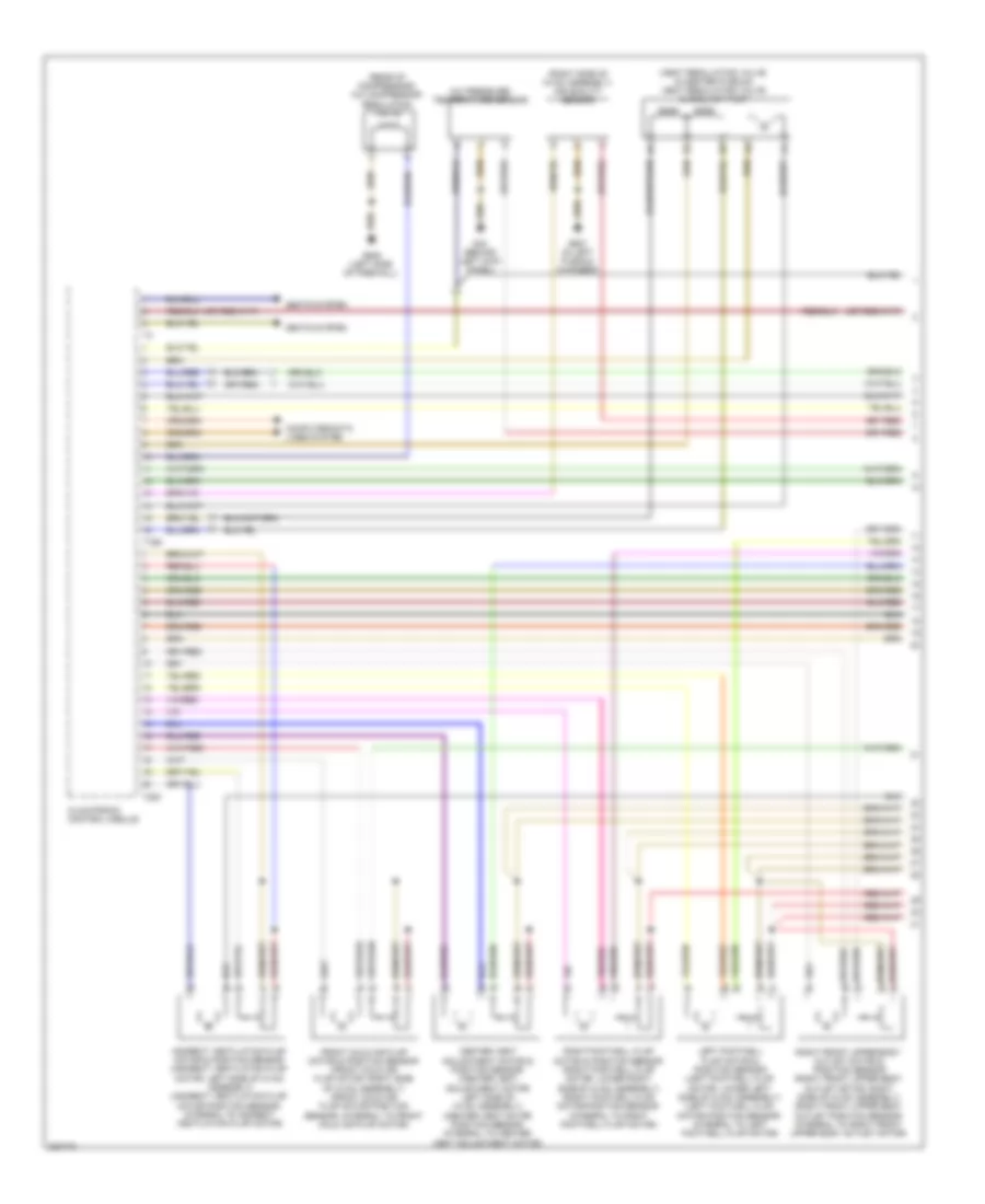
Automatic A/C Wiring Diagram (1 of 4) for Audi S6 Quattro 2010
List of elements for Automatic A/C Wiring Diagram (1 of 4) for Audi S6 Quattro 2010:
- (heat regulating valve: in center plenum) heat regulating valve & coolant pump
- (rear of compressor) a/c compressor regulation valve
- (right side of hvac assembly) air quality sensor
- A/c pressure/ temperature sensor
- Center vent adjustment motor & position sensor (center vent adjustment motor: left side of hvac assembly) (center vent motor position sensor: integral to center vent adjustment motor)
- Climatronic control module
- Computer data lines system
- Front cold air flap motor & position sensor (front cold air flap motor: right side of hvac assembly) (front cold air flap motor position sensor: integral to front cold air flap motor)
- G44 (behind left kick panel)
- G607 (in left plenum chamber)
- G645 (left side of firewall)
- Indirect ventilation flap motor & position sensor (indirect ventilation flap motor: left side of hvac assembly) (indirect ventilation flap motor position sensor: integral to indirect ventilation flap motor)
- Left footwell flap motor & position sensor (left footwell flap motor: lower left side of hvac assembly) (left footwell flap motor position sensor: integral to left footwell flap motor)
- Right footwell flap motor & position sensor (right footwell flap motor: lower right side of hvac assembly) (right footwell flap motor position sensor: integral to right footwell flap motor)
- Right front upper body outlet motor & position sensor (right front upper body outlet motor: right side of hvac assembly) (right front upper body outlet position sensor: integral to right front upper body outlet motor)
- Seats system
- T16d
- T20f
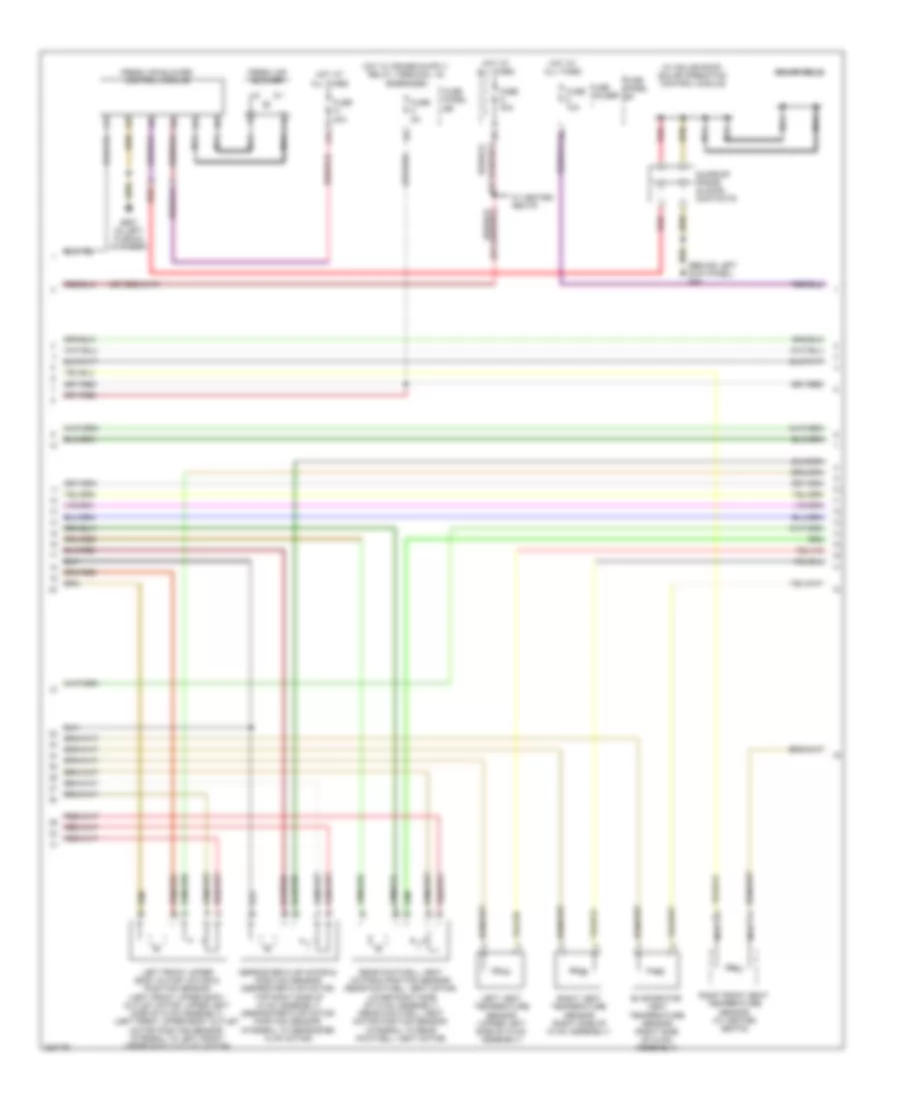
Automatic A/C Wiring Diagram (2 of 4) for Audi S6 Quattro 2010
List of elements for Automatic A/C Wiring Diagram (2 of 4) for Audi S6 Quattro 2010:
- (behind left kick panel) g44
- (w/ solar roof) solar operation control module
- 41a
- Defroster flap motor & position sensor (defroster flap motor: top right side of hvac assembly) (defroster flap motor position sensor: integral to defroster flap motor)
- Evaporator vent temperature sensor (right side of hvac assembly)
- Fresh air blower
- Fresh air blower control module
- Fuse 10a
- Fuse 30a
- Fuse 40a
- Fuse 5a
- Fuse holder
- Fuse panel sb
- Fuse panel sc
- G607 (in left plenum chamber)
- Hot at all times
- Left front upper body outlet motor & position sensor (left front upper body outlet motor: upper left side of hvac assembly) (left front upper body outlet motor position sensor: integral to left front upper body outlet motor)
- Left vent temperature sensor (upper left side of hvac assembly)
- Nca
- Rear footwell vent motor & position sensor (rear footwell vent motor: lower right side of hvac assembly) (rear footwell vent motor position sensor: integral to rear footwell vent motor)
- Red
- Right front seat temperature sensor (w/ heated seats)
- Right vent temperature sensor (right side of hvac assembly)
- Solar cells
- Sunroof frame sliding contacts
- W/ heated seats
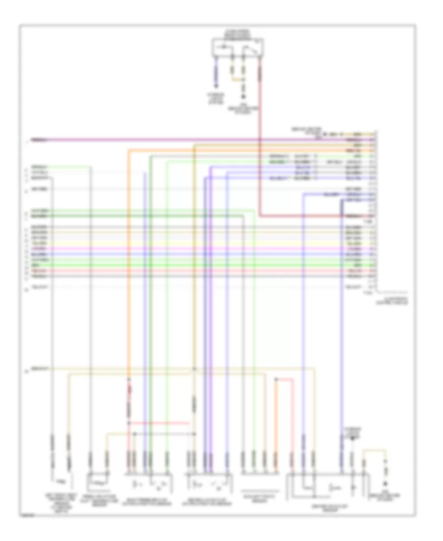
Automatic A/C Wiring Diagram (3 of 4) for Audi S6 Quattro 2010
List of elements for Automatic A/C Wiring Diagram (3 of 4) for Audi S6 Quattro 2010:
- (behind center of dash) g45
- (if equipped) rear window shade switch
- Back pressure flap motor & position sensor
- Center air outlet sensor
- Climatronic control module
- Fresh air intake duct temperature sensor
- G45 (behind center of dash)
- Interior lights system
- Left front seat temperature sensor (w/ heated seats)
- Nca
- Recirculation flap motor & position sensor
- Red
- Sunlight photo sensor
- T12a
- T16e
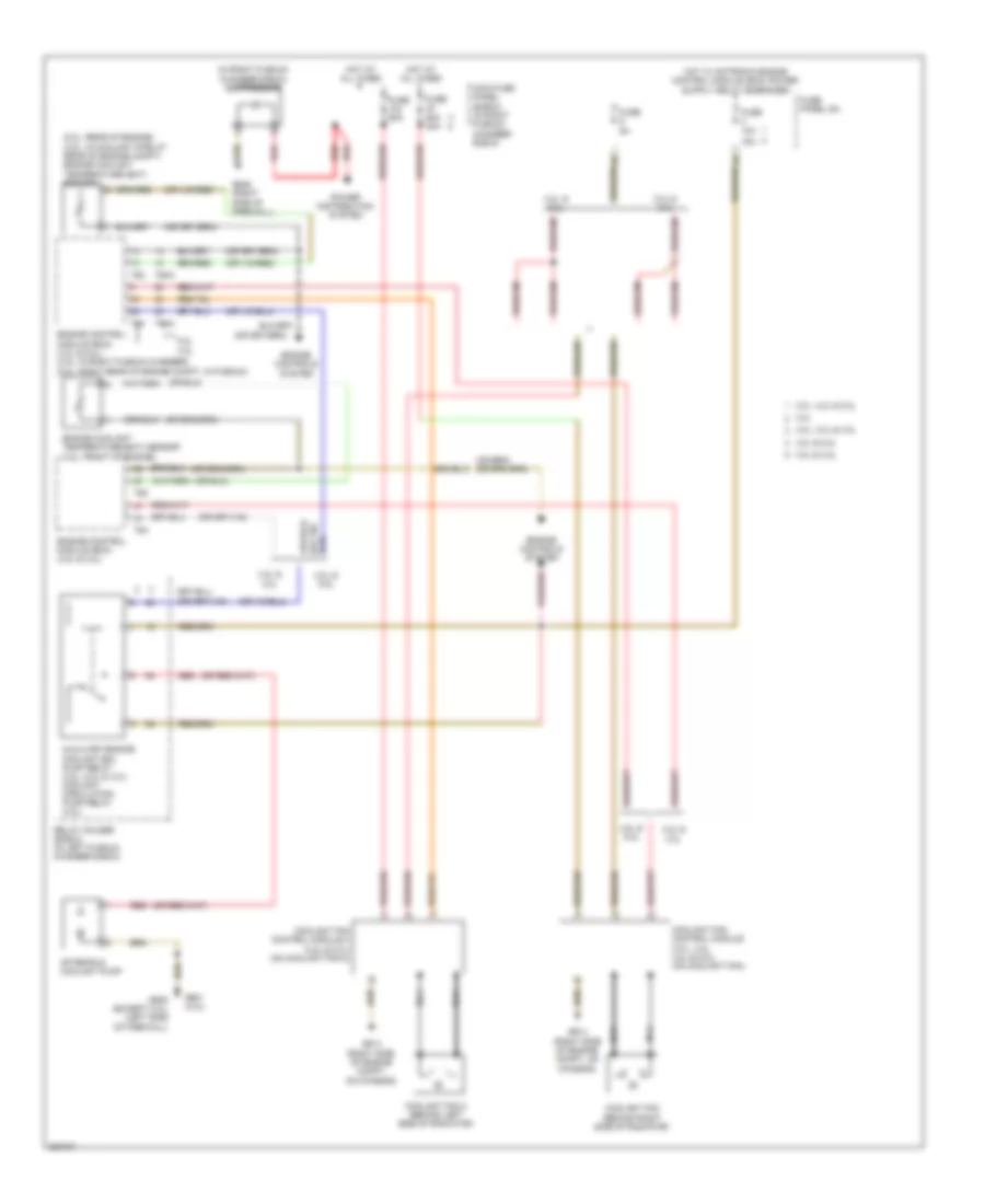
Automatic A/C Wiring Diagram (4 of 4) for Audi S6 Quattro 2010
List of elements for Automatic A/C Wiring Diagram (4 of 4) for Audi S6 Quattro 2010:
- (5.2l: rear of engine) (4.2l: in coolant pipe at rear of engine compt) engine coolant temperature (ect) sensor
- (in right plenum chamber e-box) suppressor
- 15a
- 3.0l & 3.2l
- 3.0l, 4.2l & 5.2l
- 3.2l
- 3.2l & 3.0l
- 3.2l, 3.0l & 4.2l
- 4.2l & 5.2l
- 5.2l 4.2l
- After-run coolant pump
- Auxiliary engine coolant (ec) pump relay (3.2l, 5.2l & 3.0l) coolant circulation pump relay (4.2l)
- Coolant fan (behind right side of radiator)
- Coolant fan 2 (behind left side of radiator)
- Coolant fan control module (3.0l, 3.2l, 4.2l & 5.2l) (on coolant fan)
- Coolant fan control module 2 (4.2l & 5.2l) (on coolant fan 2)
- Engine control module (ecm) (3.2l & 3.0l)
- Engine control module (ecm) (4.2l & 5.2l) (4.2l: in right plenum chamber) (5.2l: right rear of engine compt, in plenum)
- Engine controls system
- Engine coolant temperature (ect) sensor (3.2l: front of engine)
- Fuse 10a
- Fuse 5a
- Fuse 60a
- Fuse 60a 40a
- Fuse panel sa
- G601 (3.0l)
- G614 (right side of engine compt, on chassis)
- G645 (except 3.0l) (left side of firewall)
- G646 (right side of firewall)
- Hot at all times
- Main fuse panel (e-box) (in right plenum chamber e-box)
- Nca
- Power distribution system
- Red
- Relay holder (e-box) (in left plenum chamber e-box)
- T60
- T60a
- T94
- T94a

 Čeština
 Dansk
Dansk Deutsch
 Ελληνικά
 English
 Español
 Suomi
Suomi Français
 Français
 עברית
עברית Hrvatski
 Magyar
 Italiano
 日本語
日本語 한국어
한국어 Nederlands
 Polski
 Português
 Português
 Română
 Русский
 Slovenčina
 Slovenščina
 Svenska
 Türkçe
 中文 (中国)