AIR CONDITIONING
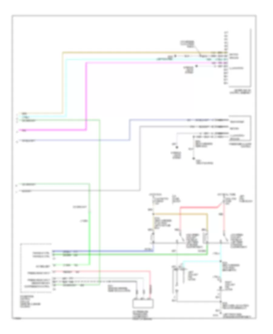
Automatic A/C Wiring Diagram (1 of 2) for Oldsmobile LSS 1999
 https://portal-diagnostov.com/license.html
Automotive Electricians Portal FZCO
Automotive Electricians Portal FZCO
https://portal-diagnostov.com/license.html
https://portal-diagnostov.com/license.html
Automotive Electricians Portal FZCO
Automotive Electricians Portal FZCO
List of elements for Automatic A/C Wiring Diagram (1 of 2) for Oldsmobile LSS 1999:
- (body harness, 8 cm from right i/p cross-channel)
- (body harness, at right wheelhouse)
- (engine harness, 6 cm from a/c compressor clutch breakout)
- (i/p harness, behind center of dash)
- (top left side of dash)
- (top right side of dash)
- +5v
- A/c clutch relay (center rear of engine compartment)
- A/c compres- sor clutch
- A/c compres- sor clutch diode
- A/c fuse 30a
- A/c request
- Ambient temperature sensor (center front of vehicle)
- Battery
- Blower control
- Blower control module (on right side of engine, near blower motor)
- Blower feedback
- Blower motor
- Clock driver
- Computer data lines system
- Data line
- Data link connector (below left side of dash)
- E10
- E11
- E12
- E13
- E14
- E15
- E16
- Enable
- F10
- F11
- F12
- F13
- F14
- F15
- F16
- Fuse 10a
- Fuse 5a 15a
- Fuse 7e 20a
- Fuse 9c 10a
- G105 (right front of engine compartment)
- G201 (right kickpad)
- Ground
- Heater and a/c programmer (behind right side of dash)
- Hot at all times
- Hot in run
- Hot in run or start
- I/p fuse block
- Ign
- Ignition
- Inside air temperature sensor (behind left side of dash)
- Left sunload sensor
- Motor ctrl
- Nca
- Pass ctrl status
- Passenger air mix valve actuator
- Pnk
- Red
- Rh i/p junction block
- Right maxi fuse block
- Right sunload sensor
- S102 (body harness, near a/c accumulator)
- S108
- S207 (body harness, 12 cm from center i/p cross-channel)
- S241 (body harness, 40 cm from lamp control module)
- S268 (body harness, 26 cm from heater and a/c programmer)
- S270
- S277
- S279 (body harness, 2 cm from end of right i/p cross- channel)
- S308 (body harn, near g203)
- Sense
- Sensor ground
- Sensor input
- Sensor return
- Signal driver
- Solar sensor input
- Tan
Automatic A/C Wiring Diagram (2 of 2) for Oldsmobile LSS 1999
List of elements for Automatic A/C Wiring Diagram (2 of 2) for Oldsmobile LSS 1999:
- (i/p harness, 12.5 cm from radio)
- (left front side of engine compartment)
- A/c pressure transducer (lower right front of engine)
- A/c request
- Clg fan/tcc fuse 5c 10a
- Compressor control
- Cool fns fuse 40a
- Fan relay ctrl
- G104
- G201 (right kickpad)
- G202 (left kick pad)
- Ground
- Heater and a/c control assembly
- High speed coolant fan relay (left rear of engine compartment)
- Hot at all times
- Hot in run
- I/p fuse block
- Ignition
- Illumination
- Interior lights system
- Left coolant fan motor
- Left maxi fuse block
- Low speed coolant fan relay (left rear of engine compartment)
- Nca
- Passenger climate control
- Powertrain control module (near air cleaner housing)
- Pressure sw input
- Red
- Return
- Right coolant fan motor
- S104 (body harness, 27 cm from left maxi fuse box)
- S121 (engine harness, near accumulator)
- S124 (body harness, 10 cm from ebcm/ebtcm)
- S128 (body harn, 6.5 cm from fan motor breakout)
- S213
- S308 (body harness, near g203)
- Sensor return
- Temp offset
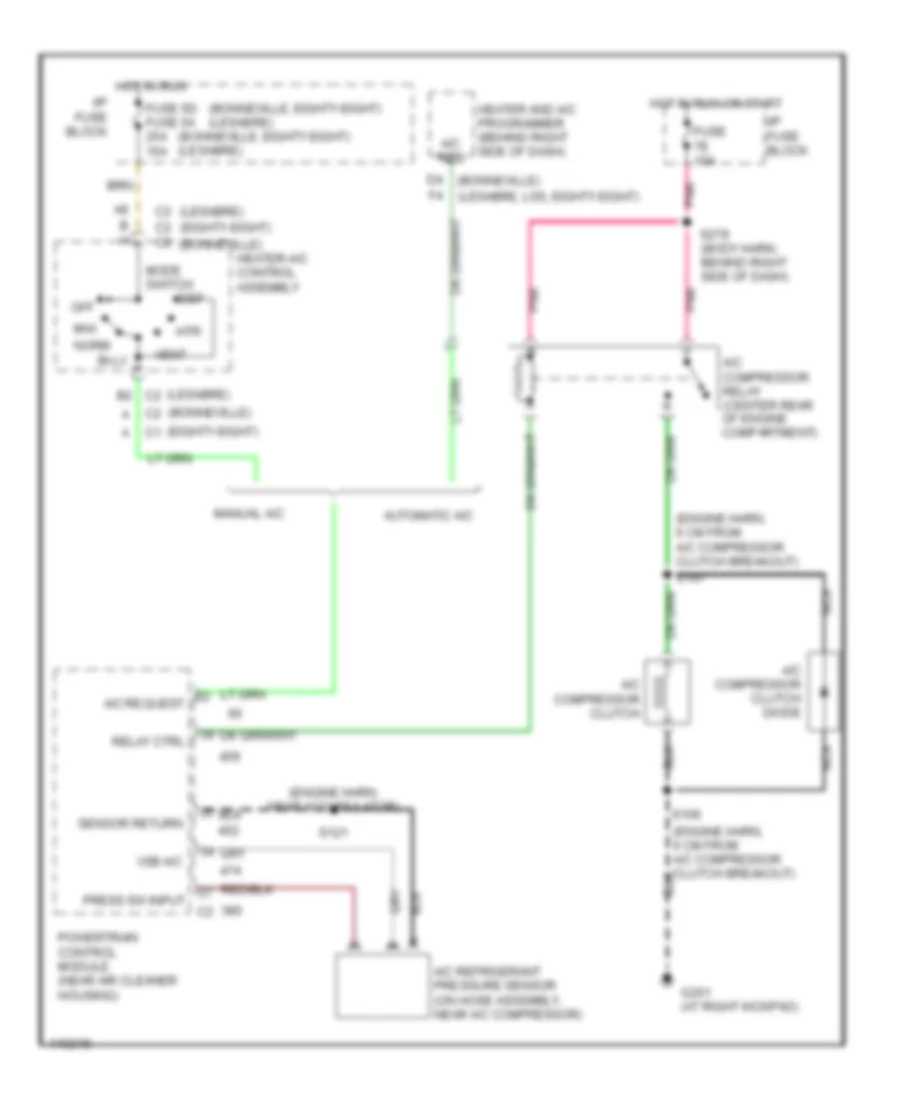
Compressor Wiring Diagram for Oldsmobile LSS 1999
List of elements for Compressor Wiring Diagram for Oldsmobile LSS 1999:
- (bonneville)
- (bonneville, eighty-eight) (lesabre)
- (eighty-eight)
- (engine harn, 6 cm from a/c compressor clutch breakout)
- (engine harn, near accumulator)
- (lesabre)
- A/c compressor clutch
- A/c compressor clutch diode
- A/c compressor relay (center rear of engine compartment)
- A/c refrigerant pressure sensor (on hose assembly, near a/c compressor)
- A/c req
- A/c request
- Automatic a/c
- B h
- Bi-lv
- C2 c2
- D4 (bonneville)
- Def
- F4 (lesabre, lss, eighty-eight)
- Fuse 5d fuse 5a 25a 15a
- Fuse 7e 10a
- G201 (at right kickpad)
- Heater and a/c programmer (behind right side of dash)
- Heater-a/c control assembly
- Hot in run
- Hot in run or start
- Htr
- I/p fuse block
- Manual a/c
- Max
- Mode switch
- Nca
- Norm
- Off
- Pnk
- Powertrain control module (near air cleaner housing)
- Press sw input
- Relay ctrl
- S106
- S107
- S121
- S279 (body harn, behind right side of dash)
- Sensor return
- Vent
- Vsb a/c
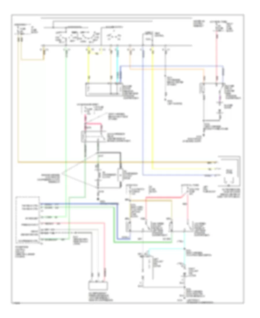
Manual A/C Wiring Diagram for Oldsmobile LSS 1999
List of elements for Manual A/C Wiring Diagram for Oldsmobile LSS 1999:
- (body harness, behind right side of dash)
- (engine harness, 6 cm from a/c compressor clutch breakout)
- (left front of engine compartment)
- A/c compressor clutch
- A/c compressor clutch diode
- A/c compressor relay (center rear of engine compartment)
- A/c fuse 30a
- A/c refrigerant pressure sensor (on hose assembly, near a/c compressor)
- A/c request
- A/c temperature valve actuator (behind center of dash, top of plenum)
- Bi-lv
- Blower motor
- Blower motor resistor (center rear of engine compartment)
- Blower relay (center rear of engine compartment)
- Blower switch
- C tan
- Clg fan/tcc fuse 5c 10a
- Compressor ctrl
- Cool
- Cool fns fuse 40a
- Def
- Fan relay ctrl
- Fuse 5d 25a
- Fuse 7e 10a
- G104
- G105 (right front of engine compt)
- G202 (left kickpad)
- G203 (at right kickpad)
- Heater-a/c control assembly
- High speed coolant fan relay (left rear of engine compartment)
- Hot at all times
- Hot in run
- Hot in run or start
- Htr
- I/p fuse block
- Left coolant fan motor
- Left maxi fuse block
- Low speed coolant fan relay (left rear of engine compartment)
- Max
- Mode switch
- Nca
- Norm
- Off
- Pnk
- Pnk s279
- Powertrain control module (near air cleaner housing)
- Press sw input
- Red
- Right coolant fan motor
- Right maxi fuse block
- S104 (body harn, 27 cm from left maxi fuse block)
- S107
- S121 (engine harn, near accumu- lator)
- S124 (body harness, 10 cm from ebcm/ebtcm)
- S128 (body harness, 6.5 cm from fan motor breakout)
- S213 (i/p harness, behind center of dash)
- Sensor return
- Solid state
- Tan
- Temp control
- Vent
- Vsb a/c
- Warm

 Čeština
 Dansk
Dansk Deutsch
 Ελληνικά
 English
 Español
 Suomi
Suomi Français
 Français
 עברית
עברית Hrvatski
 Magyar
 Italiano
 日本語
日本語 한국어
한국어 Nederlands
 Polski
 Português
 Português
 Română
 Русский
 Slovenčina
 Slovenščina
 Svenska
 Türkçe
 中文 (中国)