СИСТЕМА ПЕРЕДАЧИ ДАННЫХ
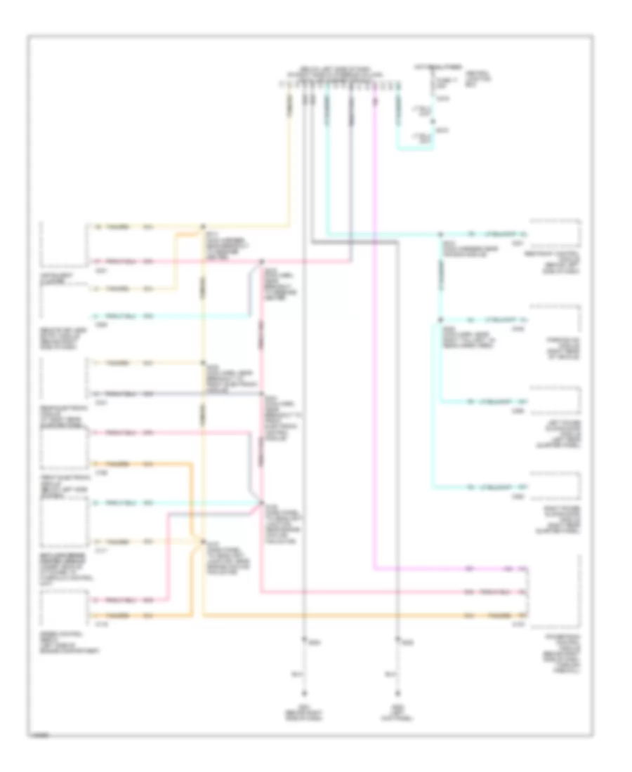
Электросхема компьютерной линии передачи данных CAN для Ford Windstar 2000
Электросхема компьютерной линии передачи данных CAN для Ford Windstar 2000 - Список элементов:
- (below left side of dash, on right side of steering column) data link connector (dlc)
- Anti-lock brake anti-lock brake control module control module (under vehicle, attached to hydraulic control unit)
- C103
- C111
- C116
- C190
- C200
- C219
- C231
- C241
- C341
- C352
- C355
- C445
- Central junction box
- Front electronic module (below left side of dash)
- Fuse 17 20a
- G200 (left kick panel)
- G201 (behind right side of dash)
- Hot at all times
- Instrument cluster
- Left power sliding door module (left rear quarter panel)
- Parking aid module (right rear of vehicle)
- Powertrain control module (behind right side of dash, through firewall)
- Rear electronic module (at right rear quarter panel)
- Remote keyless entry module (behind right side of dash)
- Restraint control module (behind left
- Right power sliding door module (right rear quarter panel)
- S137 (dash panel to headlight junction, near engine cooling fan motor)
- S138 (dash panel to headlight junction, near engine cooling fan motor)
- S208
- S210 (main harness near air bag module)
- S214 (main harness near breakout to message center)
- S215 (main harn, near breakout to message center)
- S218
- S220
- S320 (main harn, near right taillight, in) rear cargo area)
- S334 (main harn, near breakout to front electronic control module)
- S335 (main harn, near breakout to front electronic module)
- Side of dash)
- Speed control servo (left side of engine compartment)
 Čeština
 Dansk
Dansk Deutsch
 Ελληνικά
 English
 Español
 Suomi
Suomi Français
 Français
 עברית
עברית Hrvatski
 Magyar
 Italiano
 日本語
日本語 한국어
한국어 Nederlands
 Polski
 Português
 Português
 Română
 Русский
 Slovenčina
 Slovenščina
 Svenska
 Türkçe
 中文 (中国)
 English