ENGINE PERFORMANCE
6.2L FLEX FUEL
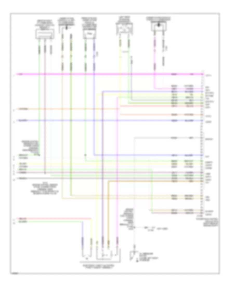
6.2L Flex Fuel, Engine Performance Wiring Diagram (1 of 6) for Ford F-250 Super Duty King Ranch 2014
 https://portal-diagnostov.com/license.html
Automotive Electricians Portal FZCO
Automotive Electricians Portal FZCO
https://portal-diagnostov.com/license.html
https://portal-diagnostov.com/license.html
Automotive Electricians Portal FZCO
Automotive Electricians Portal FZCO
List of elements for 6.2L Flex Fuel, Engine Performance Wiring Diagram (1 of 6) for Ford F-250 Super Duty King Ranch 2014:
- (customer access taped to harness near c210)
- (customer access)
- (not used)
- 10a
- A/c clutch relay
- A/c pressure transducer (right front of engine compt)
- Aat
- Accr
- Acpt
- Air conditioning system
- App1
- App2
- Apprtn
- Appvref
- Battery junction box (bjb) (left side of engine compt)
- Bpp
- Bps
- C1148
- C1168
- C1581
- C175b
- Canv
- Case gnd
- Cbb52
- Ccb08
- Cdc12
- Cdc15
- Cdc35
- Cdc38
- Ce114
- Ce237
- Ce326
- Ce436
- Ce608
- Ce912
- Ce913
- Ce914
- Ce933
- Ces09
- Cet21
- Cet42
- Cet43
- Ch302
- Cls05
- Cooling fans system
- Cto
- Digital
- Evap canister vent control solenoid (left rear side of frame)
- Evaporative emission (evap) canister purge valve (top rear of engine)
- Fcv
- Fpc
- Fpm
- Fss
- Fuse
- Fuse 10a
- Fuse 15a
- Fuse 20a
- Fuse n/a
- G103 (right rear of engine compt)
- Gd113
- Genmon
- Hot at all times
- Hot in start or run
- Iat
- Injpwrm
- Isp-r
- Le111
- Le136
- Maf
- Mass airflow/ intake air temperature (maf/iat) sensor (on engine intake air duct)
- Pcm power relay
- Pcm wake
- Pcmrc
- Powertrain control module (pcm) (right rear of engine compt)
- Pt oil
- Pto
- Pto eng
- Pto rpm
- Re136
- Re320
- S101
- S104
- S117
- Sig rtn
- Smc
- Smrc
- Sst-d
- Sst-u
- Start
- Starting/charging system
- Tron
- Trop
- Variable camshaft timing (vct 21) solenoid (front of left cylinder head)
- Vbpwr
- Ve203
- Ve225
- Ve518
- Ve701
- Ve702
- Ve740
- Ve807
- Vec10
- Vh407
- Vh433
- Vmc05
- Vref 5v
- Vsout
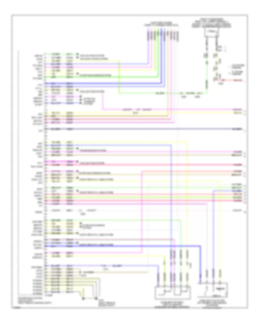
6.2L Flex Fuel, Engine Performance Wiring Diagram (2 of 6) for Ford F-250 Super Duty King Ranch 2014
List of elements for 6.2L Flex Fuel, Engine Performance Wiring Diagram (2 of 6) for Ford F-250 Super Duty King Ranch 2014:
- (engine control sensor engine compt wiring harness, near breakout to right headlamp)
- (front passenger's rear view mirror assembly) ambient air temperature (aat) sensor
- (left center of frame) fuel pump module
- Apprtn2
- Appvref2
- Battery junction box (bjb) (left side of engine compt)
- C1415
- C1581
- C175b
- C210
- C211
- C263
- C265
- C310a
- C601
- C651
- C655
- Cbb33
- Cdc10
- Ce515
- Ce608
- Computer data lines system
- Cr167
- Ens
- Fpc
- Fpm
- Fppwr
- Fprtn
- Ftp
- Fuel pump (fp) relay
- Fuel pump control module (left center of frame)
- Fuse 10a
- Fuse 20a
- G103 (right rear of engine compt)
- G136 (wide frame/narrow frame w/ mid fuel tank) (center of left frame rail)
- G402 (narrow frame w/ aft fuel tank) (left side of frame, near axle)
- Gd113
- Gd177
- Gencom
- Gnd
- Hot at all times
- Hs can +
- Hs can -
- Instrument cluster system
- Kapwr
- Le137
- Le230
- Le424
- Nca
- Powertrain control module (pcm) (right rear of engine compt)
- Pwr gnd
- R/s
- Re137
- Re407
- Re515
- Restraints control module (rcm) (under center console)
- S100
- S156 (engine control sensor engine compt wiring harness, near breakout to c1581)
- S196 (wide frame/narrow frame w/ mid fuel tank) s462 (narrow frame w/ aft fuel tank)
- Sbb72
- Sig rtn
- Sigrtn
- Sst-d
- Sst-u
- Starting/charging system
- Tow haul switch
- Tows
- Vdb04
- Vdb05
- Ve225
- Ve518
- Ve922
- Vpwr
- Vpwr fuel
- Vref
- W/ power mirrors
- W/o power mirrors
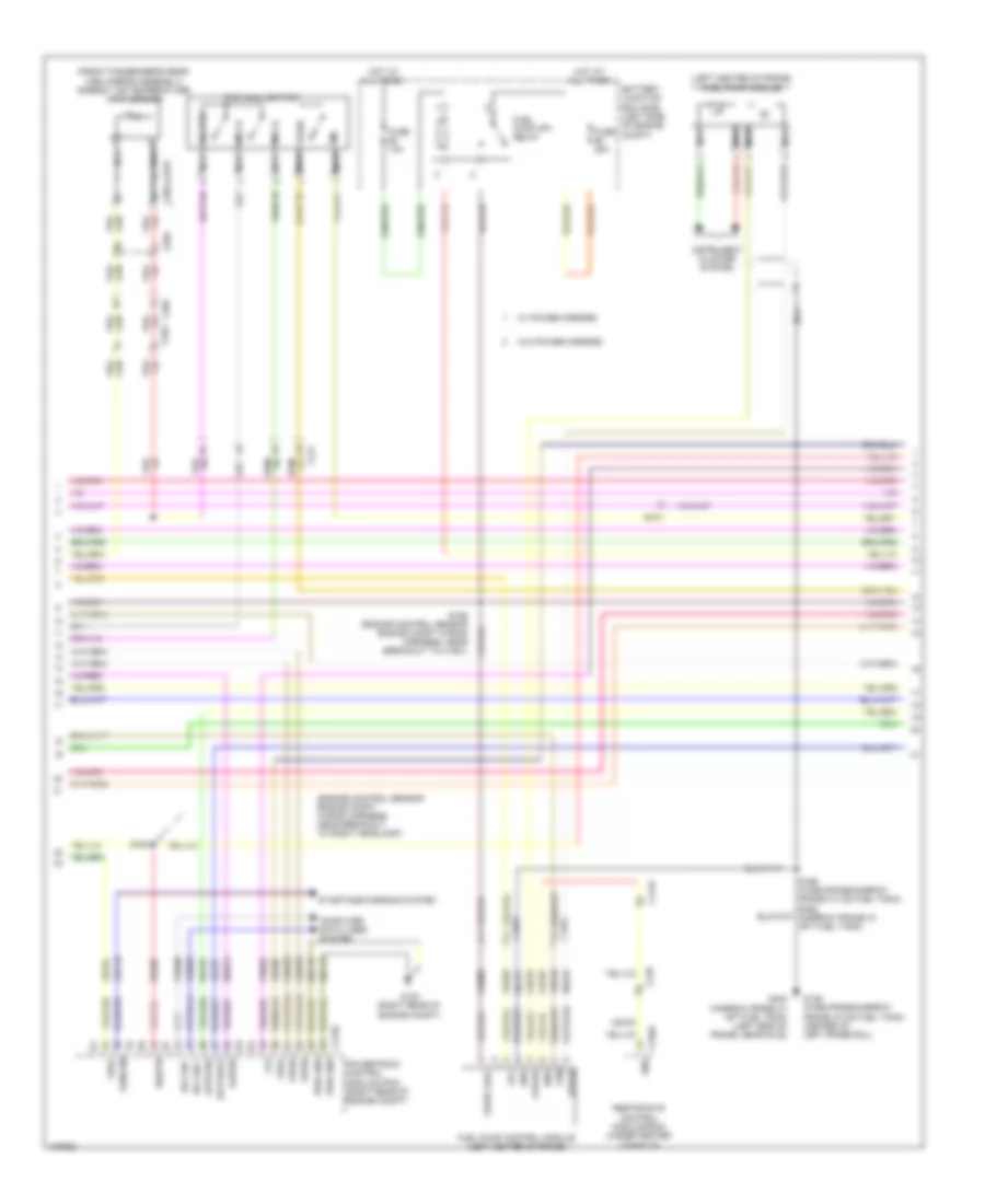
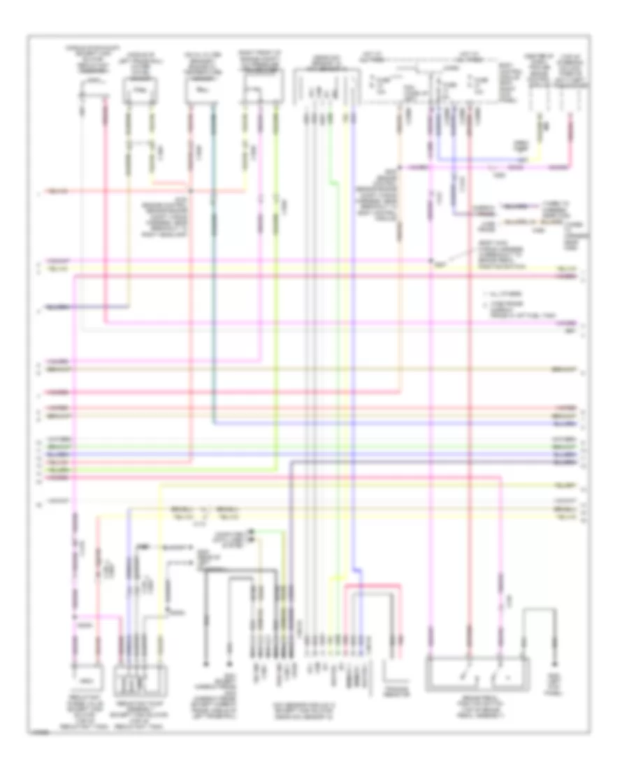
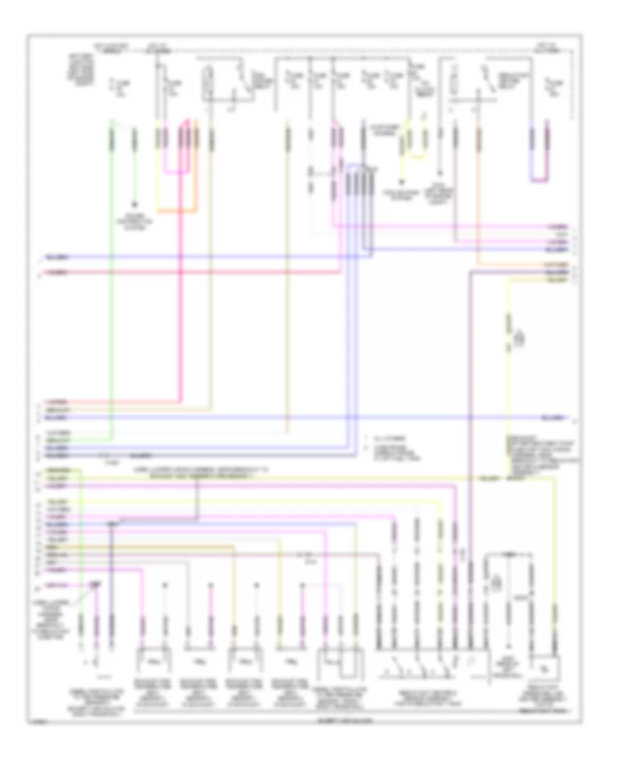
6.2L Flex Fuel, Engine Performance Wiring Diagram (3 of 6) for Ford F-250 Super Duty King Ranch 2014
List of elements for 6.2L Flex Fuel, Engine Performance Wiring Diagram (3 of 6) for Ford F-250 Super Duty King Ranch 2014:
- (body main wiring harness, in breakout to brake pedal position switch) s207
- (center of dash) trailer brake control (tbc) module
- (taped to harness near c422)
- (taped to harness near c465)
- (top of fuel tank) fuel tank pressure (ftp) transducer sensor
- (top of steering column) passive anti-theft transceiver
- (transmission wiring harness, in breakout to torqshift 6 transmission) s182
- Body control module (bcm) (right kick panel)
- Boo
- C1415
- C1581
- C2108
- C212
- C2280b
- C2280d
- C2280f
- C263
- C465
- Crew chief
- Fuel pump (fet)
- Fuse 10a
- Fuse 5a
- Hot at all times
- Hot in start or run
- Lpc
- Micro
- Narrow frame
- Oss
- Pcm wake up (fet)
- S200 (engine control sensor engine compt wiring harness, near breakout to body control module)
- S227
- Ssa
- Ssb
- Ssc
- Ssd
- Sse
- Tcc
- Tftin
- Tftout/sigrtn
- Torqshift 6 transmission
- Trgnd
- Trs/ tr-p
- Tspc1
- Tspc2
- Tss
- Vbpwr
- Wide frame
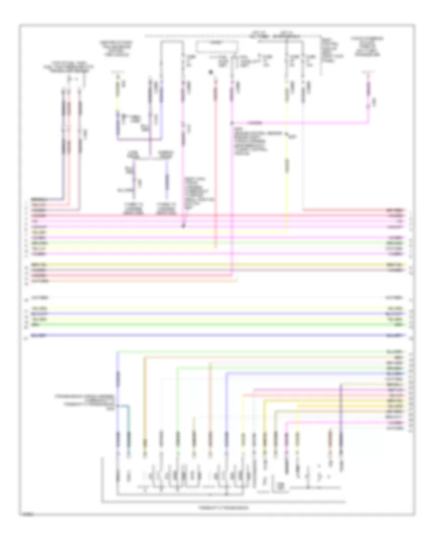
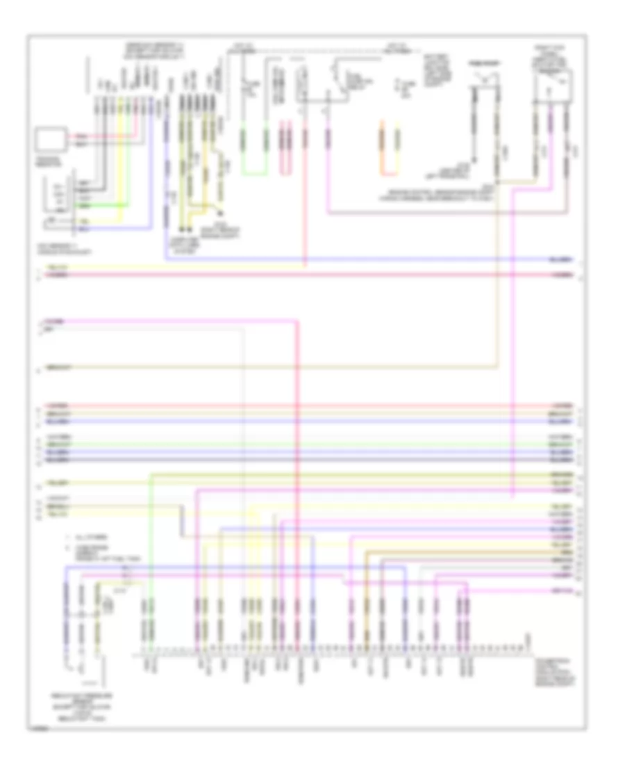
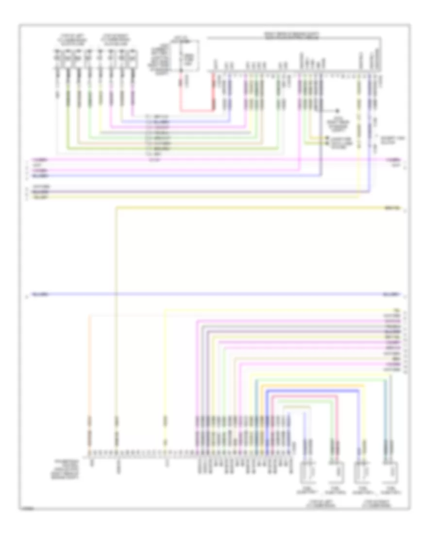
6.2L Flex Fuel, Engine Performance Wiring Diagram (4 of 6) for Ford F-250 Super Duty King Ranch 2014
List of elements for 6.2L Flex Fuel, Engine Performance Wiring Diagram (4 of 6) for Ford F-250 Super Duty King Ranch 2014:
- (accelerator pedal support) accelerator pedal position sensor
- (left exhaust, downstream of catalytic converter) heated oxygen sensor (ho2s) 22
- (left exhaust, upstream of catalytic converter) universal heated oxygen sensor (ho2s) 21
- (right exhaust, downstream of catalytic converter) heated oxygen sensor (ho2s) 12
- (right exhaust, upstream of catalytic converter) universal heated oxygen sensor (ho2s) 11
- (top of brake pedal assembly) brake pedal position switch
- (transmission wiring harness, near breakout to universal heated oxygen sensor 11) s180
- C145
- C175t
- C210
- Cat15
- Ce233
- Ce234
- Ce235
- Ce236
- Cet05
- Cet06
- Cet07
- Cet08
- Cet09
- Cet22
- Cet25
- Cet49
- Cet50
- G300 (left kick panel)
- Ho2s12
- Ho2s22
- Htr12
- Htr22
- Le111
- Le448
- Le449
- Le450
- Le451
- Le452
- Le453
- Lpc
- Nca
- Oss hall
- Powertrain control module (pcm) (right rear of engine compt)
- Re242
- Re406
- Red
- Ret04
- Ret24
- S181
- Sigrtn
- Ssa
- Ssb
- Ssc
- Ssd
- Sse
- Tcc
- Tftin
- Tftout/sigrtn
- Tows
- Trgnd
- Trp
- Tspc1
- Tss hall
- Uo2s11
- Uo2s21
- Uo2sgref11
- Uo2sgref21
- Uo2shtr11
- Uo2shtr21
- Uo2spc11
- Uo2spc21
- Uo2spct11
- Uo2spct21
- Vbpwr
- Ve730
- Ve733
- Ve826
- Ve827
- Vet27
- Vet33
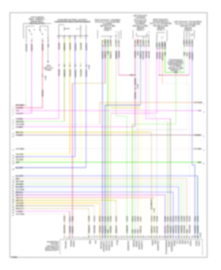
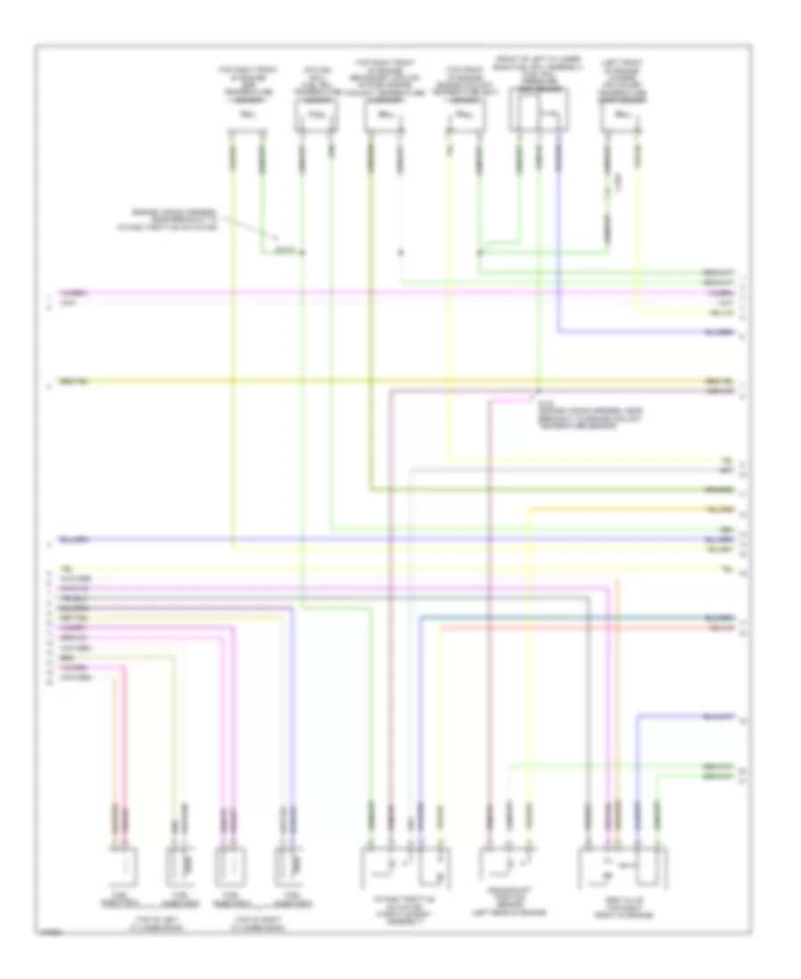
6.2L Flex Fuel, Engine Performance Wiring Diagram (5 of 6) for Ford F-250 Super Duty King Ranch 2014
List of elements for 6.2L Flex Fuel, Engine Performance Wiring Diagram (5 of 6) for Ford F-250 Super Duty King Ranch 2014:
- (coil on plugs 1, 2, 3, & 4: top of right valve cover) (coil on plugs 5, 6, 7 & 8: top of left valve cover) coil on plug (cop)
- (front of right cylinder head) variable camshaft timing (vct 11) solenoid
- (near breakout to fuel injector 3) s119
- (rear of left cylinder bank) camshaft position sensor 21 (cmp 21)
- (top left front of engine) ignition transformer capacitor 2
- (top right front of engine) ignition transformer capacitor 1
- C1168
- C175e
- Ce205
- Ce206
- Ce207
- Ce208
- Ce209
- Ce210
- Ce211
- Ce212
- Ce303
- Ce304
- Ce308
- Ce310
- Ce412
- Ce426
- Cop1a
- Cop2h
- Cop6e
- Cop8d powertrain control module (pcm) (right rear of engine compt)
- Fuel injectors (fuel injectors 1, 2, 3 & 4: top of right cylinder bank) (fuel injectors 5, 6, 7 & 8: top of left cylinder bank)
- Inj-1
- Inj-2
- Inj-3
- Inj-4
- Inj-5
- Inj-6
- Inj-7
- Inj-8
- S113 (near breakout to fuel injector 6)
- S114
- S118
- Tacm +
- Tacm -
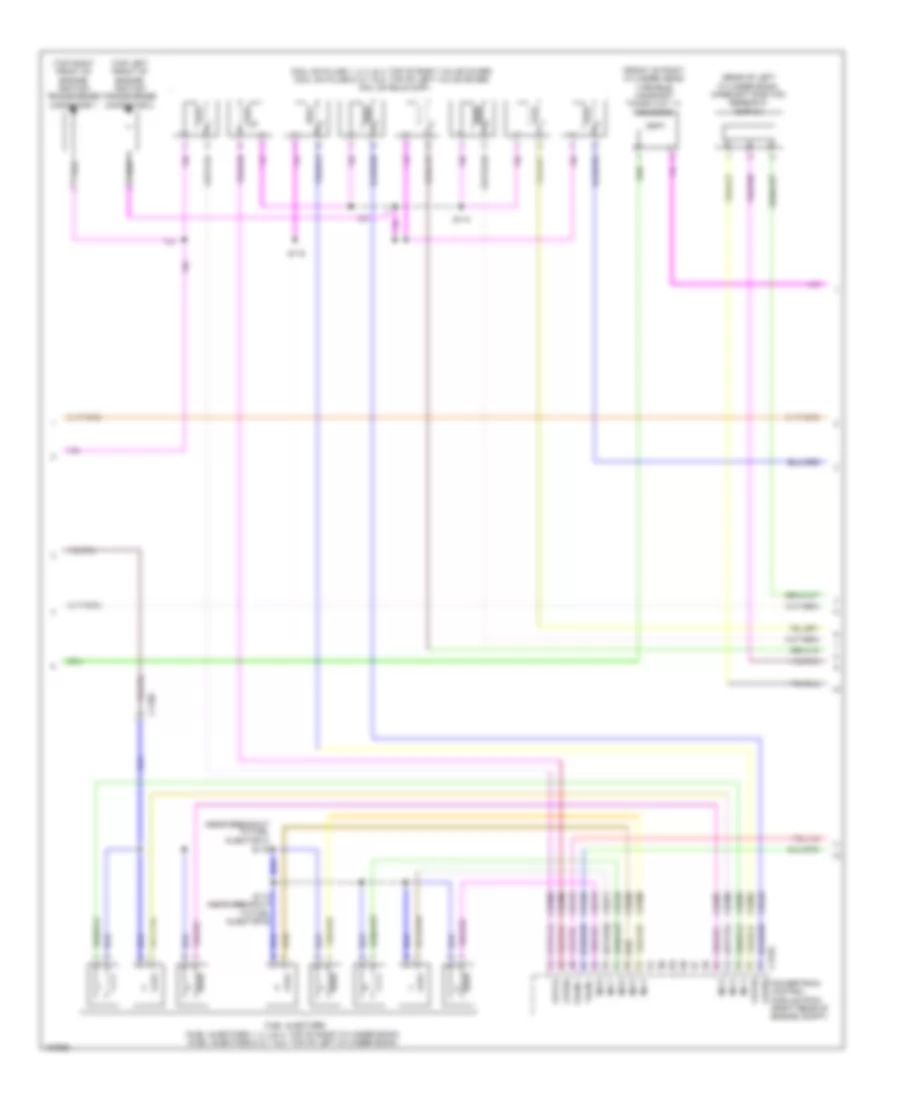
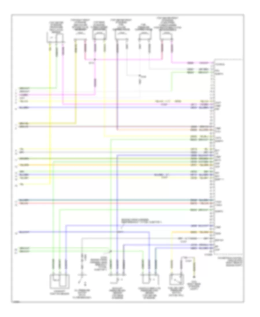
6.2L Flex Fuel, Engine Performance Wiring Diagram (6 of 6) for Ford F-250 Super Duty King Ranch 2014
List of elements for 6.2L Flex Fuel, Engine Performance Wiring Diagram (6 of 6) for Ford F-250 Super Duty King Ranch 2014:
- (engine control sensor & fuel charge wiring harness, near breakout to c1168) s120
- (engine control sensor & fuel charge wiring harness, near breakout to c133) s116
- (left rear of engine) crankshaft position sensor
- (not used)
- (rear of block, under intake manifold) cylinder head temperature (cht) sensor
- (rear of right cylinder bank) camshaft position sensor 11 (cmp 11)
- (under intake manifold, in left cylinder bank) knock sensor 2
- (under intake manifold, in right cylinder bank) knock sensor 1
- C1168
- C133
- C175e
- Ce113
- Ce305
- Ce306
- Ce307
- Ce309
- Ce421
- Ce422
- Cht
- Ckp+
- Ckp-
- Cmc24
- Cmp11
- Cmp21
- Cop3f
- Cop4c
- Cop5b
- Cop7g
- De135
- Electronic throttle control (throttle body assembly)
- Eop-sw
- Etc ref
- Etc rtn
- Evapcp
- Ks1+
- Ks1-
- Ks2+
- Ks2-
- Le111
- Le134
- Oil pressure switch (lower left front of engine)
- Powertrain control module (pcm) (right rear of engine compt)
- Re134
- Re135
- Re323
- Re324
- Re405
- S115 (engine control sensor & fuel charge wiring harness, near breakout to evaporative emission purge valve)
- Shd rtn
- Sigrtn
- Tp1
- Tp2
- Vct11
- Vct21
- Ve711
- Ve712
- Ve736
- Ve738
- Ve801
- Ve802
- Ve818
- Ve819
- Vref
6.7L TURBO DIESEL
6.7L Turbo Diesel, Engine Performance Wiring Diagram (1 of 7) for Ford F-250 Super Duty King Ranch 2014
List of elements for 6.7L Turbo Diesel, Engine Performance Wiring Diagram (1 of 7) for Ford F-250 Super Duty King Ranch 2014:
- (customer access taped to harness near c210)
- (front passenger's rear view mirror assembly) (except w/ manual aero mirrors) ambient air temperature sensor
- Aat
- Accelerator pedal position sensor (accelerator pedal support)
- Accr
- Acpt
- Air conditioning system
- App
- App2
- Apprtn
- Apprtn2
- Appvref
- Appvref2
- Bcp lamp
- Bcp sw
- Bpp
- Bps
- C1232b
- C210
- C263
- C265
- C601
- C651
- C655
- Can2 high
- Can2 low
- Cbb33
- Cbb52
- Ccb08
- Cdc09
- Cdc12
- Cdc15
- Cdc35
- Cdc38
- Cdc47
- Cdc48
- Ce140
- Ce226
- Ce237
- Ce326
- Ce436
- Ce911
- Ce912
- Ce913
- Ce914
- Ce926
- Ce933
- Ces09
- Cet40
- Ch302
- Computer data lines system
- Cooling fans system
- Cto
- Digital
- Fc-v
- Fdsom
- Fpc
- Fpm
- Fss
- G103 (right rear of engine compt)
- Gd113
- Gencom
- Genmon
- Hs can+
- Hs can-
- Iat
- Isp-r
- Kapwr
- Le111
- Le136
- Le137
- Le424
- Le434
- Maf
- Mass air flow/intake air temperature sensor (on engine intake air duct)
- Nca
- Pcm wake
- Pcmrc
- Powertrain control module (pcm) (right rear of engine compt)
- Pt oil
- Pto
- Pto eng
- Pto ref
- Pto rpm
- Pto rtn
- Pwrgnd
- Re136
- Re137
- Re320
- Re327
- Re407
- S105
- Sbb72
- Sigrtn
- Smc
- Smrc
- Start
- Starting/ charging system
- Starting/charging system
- Transmissions system
- Trsw-pn
- Vbpwr
- Vdb04
- Vdb05
- Ve203
- Ve348
- Ve349
- Ve518
- Ve701
- Ve702
- Ve740
- Ve807
- Ve823
- Vec10
- Vh407
- Vh433
- Vmc05
- Vpwr
- Vref
- Vref 5v
- Vsout
- W/ power mirrors
- W/o power mirrors
- Wif
6.7L Turbo Diesel, Engine Performance Wiring Diagram (2 of 7) for Ford F-250 Super Duty King Ranch 2014
List of elements for 6.7L Turbo Diesel, Engine Performance Wiring Diagram (2 of 7) for Ford F-250 Super Duty King Ranch 2014:
- (body main wiring harness, in breakout to brake pedal position switch)
- (center of dash) trailer brake control module
- (middle of exhaust) (except high sulfur) reductant injector
- (middle of left frame rail) water- in-fuel sensor
- (near nox sensor 12) nox sensor 12
- (on oil filter bracket) engine oil temperature sensor
- (right front of engine compt) a/c pressure transducer
- (taped to harness near c422)
- (top of steering column) passive anti-theft transceiver
- 10a
- All others
- B00
- Body control module (bcm) (right kick panel)
- Brake pedal position switch (top of brake pedal assembly)
- C1046
- C110
- C139 c3047
- C1415
- C1581
- C210
- C2108
- C212
- C2280b
- C2280d
- C2280f
- C263
- C3047 c139
- C3611a
- C3611b
- C465
- Can2 +
- Can2 -
- Cbb36
- Ccb08
- Com
- Computer data lines system
- Crew chief
- Fuse
- G300 (left kick panel)
- G400 (rear of left frame rail)
- G401 (except narrow frame) g403 (narrow frame) (except narrow frame: middle of left frame rail)
- Gd180
- Gnd
- Heater +
- Heater -
- Hot at all times
- Ip1
- Ip2
- Memory +
- Memory -
- Micro
- Narrow frame
- Narrow frame w/ aft fuel tank
- Nca
- Nox sensor module 12 (except high sulfur) (near nox sensor 12)
- Pcm wake up (fet)
- Pnk
- Pwr gnd
- Rdpc
- Reductant pump assembly (except high sulfur) (top of reductant tank)
- Reductant purge valve (except high sulfur) (top of reductant tank)
- S100 (engine control sensor engine compt wiring harness, near breakout to right headlamp)
- S207
- S3000
- S3002
- S405
- Sig gnd
- Trimming resistor
- Ve348
- Ve349
- Vpwr
- Vs +
- Wide frame
- Wide frame/
6.7L Turbo Diesel, Engine Performance Wiring Diagram (3 of 7) for Ford F-250 Super Duty King Ranch 2014
List of elements for 6.7L Turbo Diesel, Engine Performance Wiring Diagram (3 of 7) for Ford F-250 Super Duty King Ranch 2014:
- (near nox sensor 11) (except high sulfur) nox sensor module 11
- (right kick panel) inertia fuel shutoff (ifs) switch
- 20a
- All others
- Battery junction box (bjb) (left side of engine compt)
- C110
- C1232t
- C146
- C1581
- C211
- C3047 c139
- C3619a
- C3619b
- Can2 +
- Can2 -
- Cbb36
- Ce354
- Ce355
- Com
- Computer data lines system
- Dpf
- Dpf12
- Egt 11
- Egt 12
- Egt 13
- Egt 14
- Fuel pump
- Fuel pump (fp) motor diode
- Fuel pump (fp) relay
- Fuse
- Fuse 10a
- G103 (right rear of engine compt)
- G135 (center of left frame rail)
- Gd113
- Heater +
- Heater -
- Hot at all times
- Ip1
- Ip2
- Le425
- Le461
- Memory +
- Memory -
- Nca
- Nox sensor 11 (middle of exhaust)
- Pnk
- Powertrain control module (pcm) (right rear of engine compt)
- Pwr gnd
- Rdinjgnd
- Rdinjpwr
- Rdl1
- Rdl2
- Rdl3
- Rdlrtn
- Rdp
- Rdpc
- Rdpgc
- Rdt
- Re406
- Re839
- Reductant pressure sensor (except high sulfur) (top of reductant tank)
- S124 (engine control sensor engine compt wiring harness, near breakout to c1581)
- Sig gnd
- Sigrtn
- Trimming resistor
- Ve348
- Ve349
- Ve350
- Ve351
- Ve713
- Ve722
- Ve726
- Ve747
- Ve752
- Ve754
- Ve833
- Ve838
- Ve839
- Ve840
- Ve841
- Vpwr
- Vref
- Vs +
- Wide frame/ narrow frame w/ aft fuel tank
6.7L Turbo Diesel, Engine Performance Wiring Diagram (4 of 7) for Ford F-250 Super Duty King Ranch 2014
List of elements for 6.7L Turbo Diesel, Engine Performance Wiring Diagram (4 of 7) for Ford F-250 Super Duty King Ranch 2014:
- (customer access)
- (exhaust aftertreatment pump injector tank wiring harness, near breakout to reductant heater & sensor assembly) s3001
- (urea jumper wiring harness, near breakout to exhaust gas temperature sensor 1)
- (urea jumper wiring harness, near breakout to reductant injector)
- 10a
- A/c clutch relay
- All others
- Battery junction box (bjb) (left side of engine compt)
- C1047
- C110
- C139 c3047
- C1581
- Cooling fans system
- Diesel particulate filter pressure sensor 1 bank 1 (right frame rail)
- Diesel particulate filter pressure sensor 2 (except high sulfur) (right frame rail)
- Except high sulfur
- Exhaust gas temperature (egt) sensor 1 (in exhaust)
- Exhaust gas temperature (egt) sensor 2 (in exhaust)
- Exhaust gas temperature (egt) sensor 3 (in exhaust)
- Exhaust gas temperature (egt) sensor 4 (in exhaust)
- Fuse
- Fuse 10a
- Fuse 15a
- Fuse 25a
- Fuse n/a
- G104 (left rear of engine compt)
- G400 (rear of left frame rail)
- Hot at all times
- Hot in start or run
- Nca
- Pcm power relay
- Power distribution system
- Reductant heater & sensor assembly (top of reductant tank)
- Reductant heater relay
- Reductant pressure line heater assembly (top of reductant tank)
- S108
- S122
- S3002
- S405
- S408
- Wide frame/ narrow frame w/ aft fuel tank
6.7L Turbo Diesel, Engine Performance Wiring Diagram (5 of 7) for Ford F-250 Super Duty King Ranch 2014
List of elements for 6.7L Turbo Diesel, Engine Performance Wiring Diagram (5 of 7) for Ford F-250 Super Duty King Ranch 2014:
- (right rear of engine compt) glow plug control module
- (top of left cylinder bank)
- (top of left cylinder bank) glow plugs
- (top of right cylinder bank)
- (top of right cylinder bank) glow plugs
- 125a
- Batt
- C110
- C1147
- C1232e
- C1273a
- C1273b
- C1273c
- C146
- C1617b
- Can2 +
- Can2 -
- Cbb36
- Ccv
- Ce101
- Ce102
- Ce205
- Ce206
- Ce207
- Ce208
- Ce209
- Ce210
- Ce211
- Ce212
- Ce243
- Ce244
- Ce245
- Ce246
- Ce247
- Ce248
- Ce251
- Ce252
- Ce352
- Ce356
- Ce513
- Ce609
- Computer data lines system
- Egr
- Egrcbv
- Egrvch
- Egrvcl
- Except high sulfur
- Fuel injector 1
- Fuel injector 4
- Fuel injector 6
- Fuel injector 7
- G103 (right rear of engine compt)
- Gd113
- Gnd
- Gp1
- Gp2
- Gp3
- Gp4
- Gp5
- Gp6
- Gp7
- Gp8
- High current battery junction box (bjb) (right side of engine compt)
- Hot at all times
- Inj1
- Inj1rtn
- Inj2
- Inj2rtn
- Inj3
- Inj3rtn
- Inj4
- Inj4rtn
- Inj5
- Inj5rtn
- Inj6
- Inj6rtn
- Inj7
- Inj7rtn
- Inj8
- Inj8rtn
- Mega fuse
- Nca
- Powertrain control module (pcm) (right rear of engine compt)
- Rdhtrc1
- Rdhtrc2
- Rdhtrpc
- Rdhtrpwr
- Re205
- Re206
- Re207
- Re208
- Re209
- Re210
- Re211
- Re212
- Red
- Sbf04
- Ve348
- Ve349
- Ve721
- Ve763
- Ve917
- Vpwr
6.7L Turbo Diesel, Engine Performance Wiring Diagram (6 of 7) for Ford F-250 Super Duty King Ranch 2014
List of elements for 6.7L Turbo Diesel, Engine Performance Wiring Diagram (6 of 7) for Ford F-250 Super Duty King Ranch 2014:
- (engine wiring harness, near breakout to intake throttle actuator)
- (front of left cylinder bank fuel rail assembly) fuel rail pressure (frp) sensor
- (left front of engine) charge air cooler temperature (cact) sensor
- (on fuel rail) fuel rail temperature sensor
- (top front of engine) engine coolant temperature (ect) sensor
- (top of left cylinder bank)
- (top of right cylinder bank)
- (top right front of engine) egr temperature sensor
- (top right front of engine) secondary cooling system engine coolant temperature 2 sensor
- C1047
- Crankshaft position sensor (left rear of engine)
- Egr valve (top right front of engine)
- Fuel injector 2
- Fuel injector 3
- Fuel injector 5
- Fuel injector 8
- Intake throttle actuator (throttle body assembly)
- S1013
- S123 (engine wiring harness, near breakout to engine coolant temperature sensor)
6.7L Turbo Diesel, Engine Performance Wiring Diagram (7 of 7) for Ford F-250 Super Duty King Ranch 2014
List of elements for 6.7L Turbo Diesel, Engine Performance Wiring Diagram (7 of 7) for Ford F-250 Super Duty King Ranch 2014:
- (engine wiring harness, near breakout to fuel injector 1)
- (top center front of engine) (if equipped) turbocharger wastegate regulating valve solenoid
- (top center front of engine) fuel volume control valve
- (top center of engine) crankcase ventilation sensor
- (top rear of engine) turbocharger actuator
- (top right front of engine) egr cooler bypass valve solenoid
- C1046
- C1047
- C1232e
- Cact
- Camshaft position sensor
- Ce256
- Ce257
- Ce412
- Ce426
- Ce435
- Ce460
- Ce932
- Ckp
- Cmc24
- Cmp
- Ect
- Ect2
- Egrt 11
- Eop sw
- Eot
- Exhaust pressure (ep) sensor (top rear of engine)
- Fdps
- Fpc
- Frp
- Frt
- Fuel delivery pressure switch (on fuel rail)
- Fuel pressure control valve
- Fvcv
- G103 (right rear of engine compt)
- Le111
- Le152
- Le423
- Le458
- Manifold absolute pressure (map) sensor (top center of engine)
- Map
- Oil pressure switch (on oil filter bracket)
- Powertrain control module (pcm) (right rear of engine compt)
- Re405
- S1002 (engine wiring harness, near breakout to fuel injector 1)
- S109
- S110
- S111
- Sigrtn
- Tacm+
- Tacm-
- Tcwrvs
- Ve701
- Ve716
- Ve718
- Ve726
- Ve727
- Ve728
- Ve736
- Ve755
- Ve759
- Ve803
- Ve820
- Vgtc
- Vref

 Čeština
 Dansk
Dansk Deutsch
 Ελληνικά
 English
 Español
 Suomi
Suomi Français
 Français
 עברית
עברית Hrvatski
 Magyar
 Italiano
 日本語
日本語 한국어
한국어 Nederlands
 Polski
 Português
 Português
 Română
 Русский
 Slovenčina
 Slovenščina
 Svenska
 Türkçe
 中文 (中国)