AIR CONDITIONING
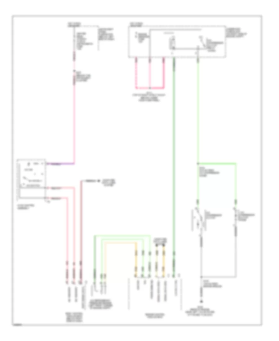
Compressor Wiring Diagram for Pontiac GTO 2006
List of elements for Compressor Wiring Diagram for Pontiac GTO 2006:
- A/c
- A/c compressor clutch
- A/c compressor clutch relay (micro)
- A/c ind
- A/c refrigerant pressure sensor (left front corner of engine compt)
- A/c request
- A/c switch
- Body control module (bcm) (below right side of dash)
- Clu rly ctrl
- Clutch
- Compressor
- Computer data lines system
- Diode
- Engine control module (ecm)
- Engine sensors fuse 15a
- G105 (rear of engine, near left valve cover, attached to block)
- Heated rear window, hvac & instruments fuse 7.5a
- Hot in run or start
- Hvac control assembly
- Instrument cluster)
- Instrument panel fuse block (below left end of dash)
- Low ref
- Pnk
- Press sens sig
- S111 (top of right strut mount, behind under hood fuse panel)
- S130 (730 mm from engine ground)
- S134 (510 mm from a/c compressor diode)
- Serial data bus +
- Serial data bus -
- Tan
- Uart serial data
- Underhood fuse block (on right side of engine compt)
- Vol
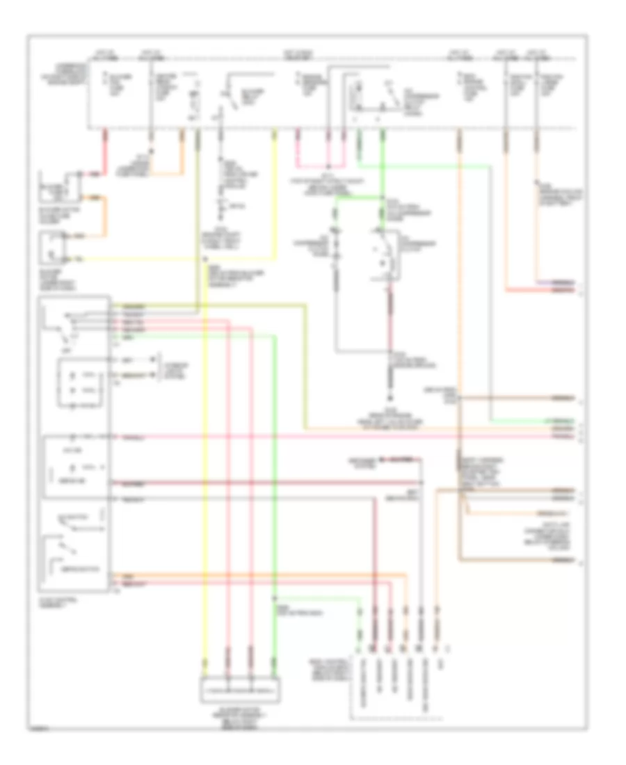
Manual A/C Wiring Diagram (1 of 2) for Pontiac GTO 2006
List of elements for Manual A/C Wiring Diagram (1 of 2) for Pontiac GTO 2006:
- (295 mm from c206) s105
- A/c compressor clutch
- A/c compressor clutch diode
- A/c compressor clutch relay (micro)
- A/c ind
- A/c request
- A/c switch
- Bat
- Bcm/ engine control fuse 15a
- Blower fan fuse 40a
- Blower fuse 30a
- Blower motor (under right side of dash)
- Blower motor inline fuse holder
- Blower motor resistor assembly (below right side of dash)
- Blower relay (mini)
- Blr mtr low ctrl
- Body control module (bcm) (below right side of dash)
- Data link connector (dlc) (under dash, below steering column)
- Defog ind
- Defog switch
- Defogger system
- Engine sensors fuse 15a
- G102 (engine compt in right front wheel well)
- G105 (rear of engine, near left valve cover, attached to block)
- Heated rear window fuse 30a
- Hot at all times
- Hot in run or start
- Hvac control assembly
- Interior lights system
- Off
- Panel, near seat bottom) s106
- Pnk
- Rad fan large fuse 30a
- Rad fan small fuse 30a
- Rear defog sw
- Red
- S111 (top of right strut mount, behind under hood fuse panel)
- S114 (inside underhood fuse panel)
- S134 (510 mm from a/c compressor diode)
- S165 (engine cooling harness, front of battery)
- S255 (355 mm from blower motor resistor assembly)
- S256 (335 mm from bcm)
- S257 (behind bcm)
- Sec rear defog sw
- Sp100
- Underhood fuse block (on right side of engine compt)
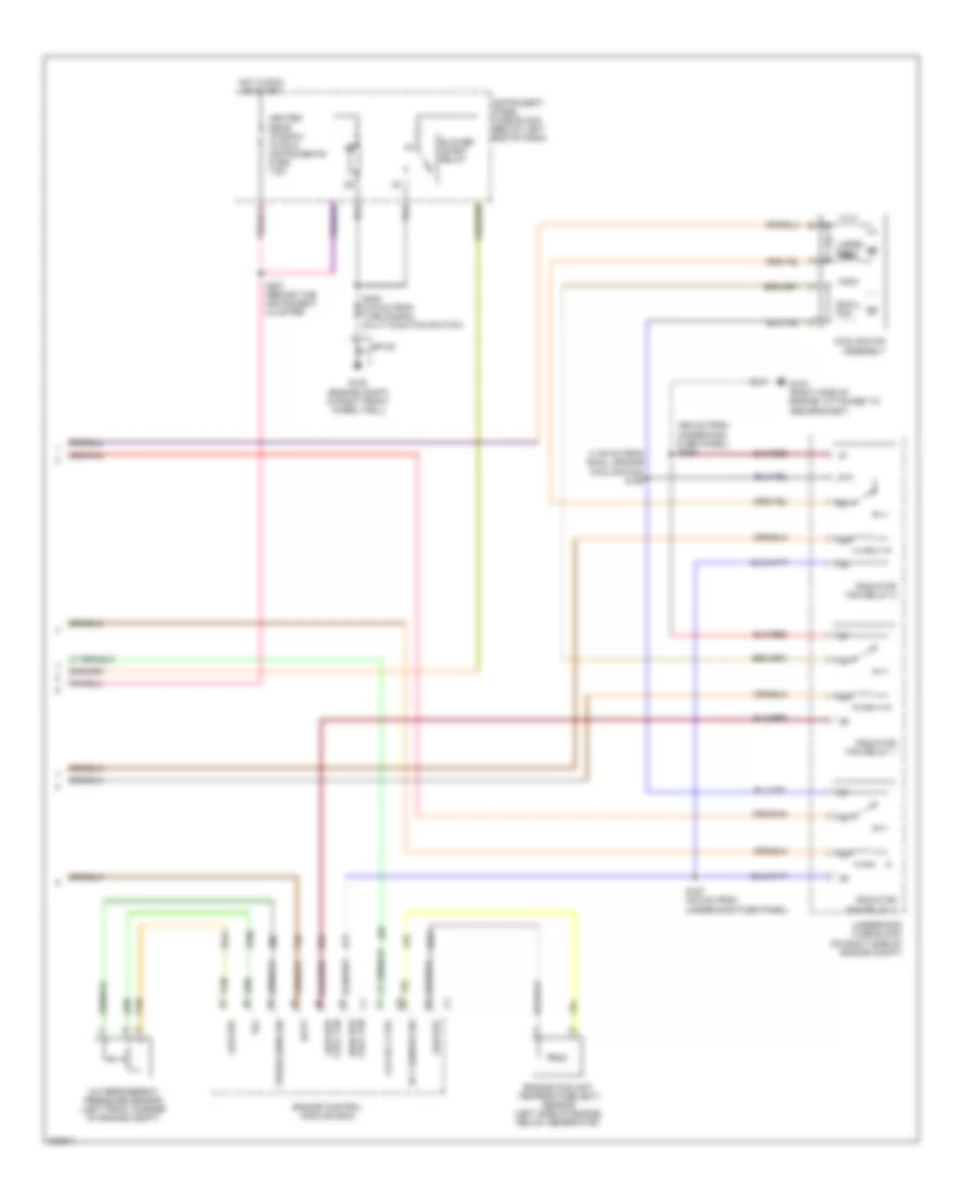
Manual A/C Wiring Diagram (2 of 2) for Pontiac GTO 2006
List of elements for Manual A/C Wiring Diagram (2 of 2) for Pontiac GTO 2006:
- (1135 mm from small engine cooling fan) s156
- (360 mm from underhood fuse panel) s239
- 87a
- A/c refrigerant pressure sensor (left front corner of engine compt)
- Batt
- Blower inhibit relay
- C1 cool fan
- Clu rly ctrl
- Cooling fan assembly
- Ect sensor sig
- Engine control module (ecm)
- Engine coolant temperature (ect) sensor (left side of engine, below generator)
- G102 (engine compt in right front wheel well)
- G103 (right side of engine, attached to abs bracket)
- Heated rear window, hvac & instruments fuse 7.5a
- High spd
- Hot in run or start
- Instrument panel fuse block (below left end of dash)
- Large fan
- Low ref
- Low spd cool fan
- Press sens sig
- Radiator fan relay 1
- Radiator fan relay 2
- Radiator fan relay 3
- S157 (275 mm from underhood fuse panel)
- S207 (behind the instrument cluster)
- Small fan
- Sp100
- Tan
- Underhood fuse block (on right side of engine compt)
- Vol

 Čeština
 Dansk
Dansk Deutsch
 Ελληνικά
 English
 Español
 Suomi
Suomi Français
 Français
 עברית
עברית Hrvatski
 Magyar
 Italiano
 日本語
日本語 한국어
한국어 Nederlands
 Polski
 Português
 Português
 Română
 Русский
 Slovenčina
 Slovenščina
 Svenska
 Türkçe
 中文 (中国)