AIR CONDITIONING
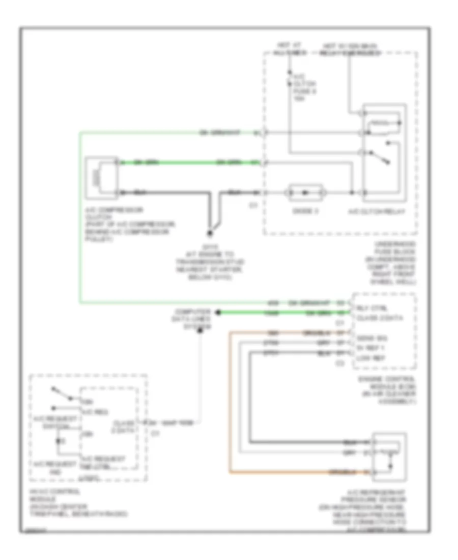
Compressor Wiring Diagram for Saturn Relay 2007
List of elements for Compressor Wiring Diagram for Saturn Relay 2007:
- 5v ref 1
- A/c cltch fuse 6 10a
- A/c cltch relay
- A/c compressor clutch (part of a/c compressor, behind a/c compressor pulley)
- A/c refrigerant pressure sensor (on high pressure hose, near high pressure hose connection to a/c compressor)
- A/c req
- A/c request
- A/c request ind ctrl
- A/c request switch
- Class 2 data
- Computer data lines system
- Diode 3
- Engine control module (ecm) (in air cleaner assembly)
- G115 (at engine to transmission stud nearest starter, below g113)
- Hot at all times
- Hot w/ ign main relay energized
- Hvac control module (in dash center trim panel, beneath radio)
- Ign
- Ind
- Logic
- Low ref
- Rly ctrl
- Sens sig
- Underhood fuse block (in underhood compt, above right front wheel well)
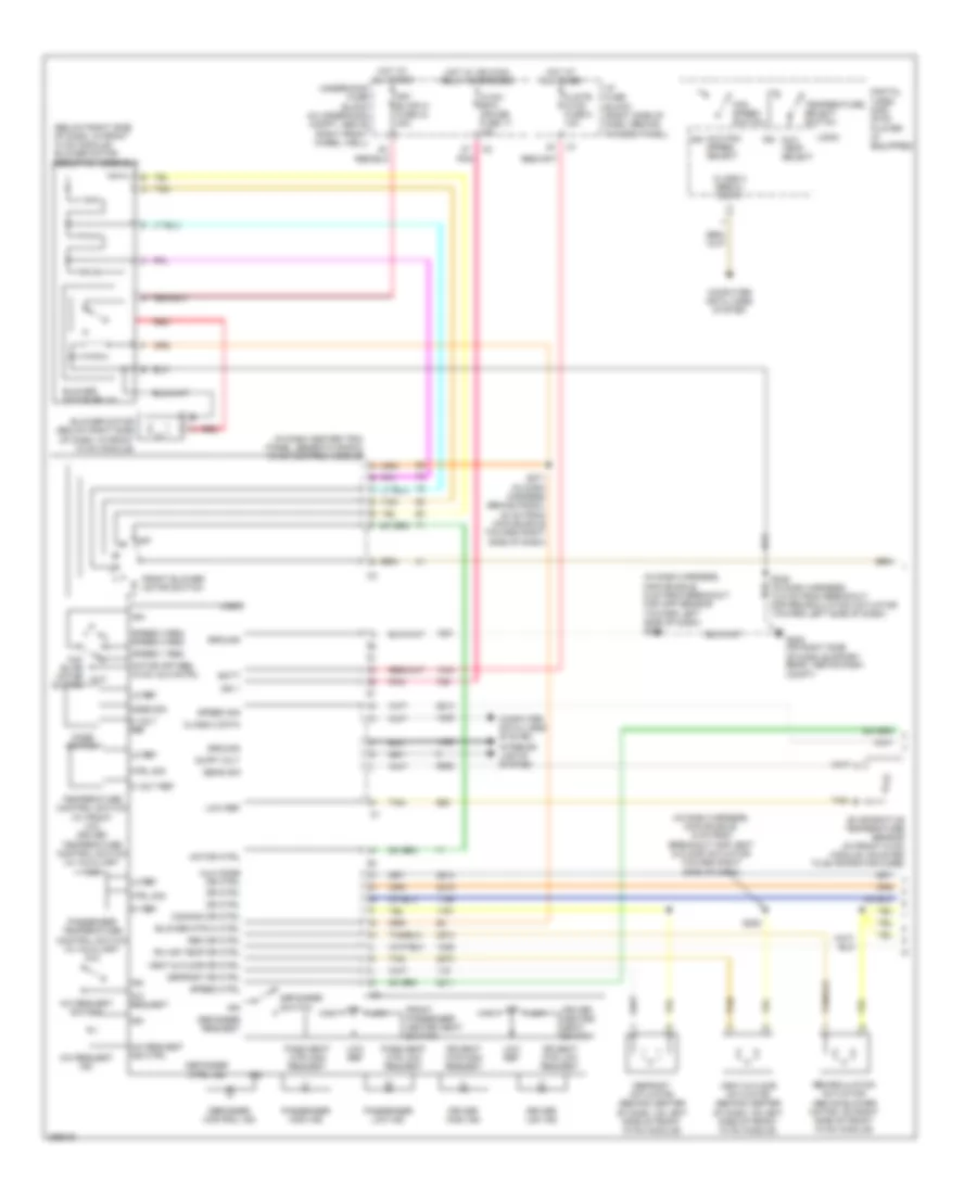
Manual A/C Wiring Diagram (1 of 2) for Saturn Relay 2007
List of elements for Manual A/C Wiring Diagram (1 of 2) for Saturn Relay 2007:
- (below right side of dash, in front hvac module) blower motor resistor assembly
- (in dash center trim panel, beneath radio) hvac control module
- (in dash harness, main bundle, 9 cm from breakout for app sensor toward left side of dash) s255
- (in dash harness, main bundle, 9 cm from breakout for vent & floor actuator toward right side of dash)
- 5 volt ref
- 5v ref
- A/c request
- A/c request ind
- A/c request ind ctrl
- A/c request switch
- Aux
- Aux blwr motor switch
- Aux fan speed select
- Aux mode dr ctrl
- Aux temp select
- B b
- Batt
- Blower motor (below right side of dash, in front hvac module)
- Blower motor relay
- Blower mtr hi ctrl
- Class 2 data
- Class 2 serial data
- Clstr/ hvac fuse 8 10a
- Commom dr ctrl
- Computer data lines system
- Ctrl sig
- Defogger control ind
- Defogger ctrl ind
- Defogger request
- Defogger switch
- Defrost actuator (behind center of dash, on left side of front hvac module)
- Defrost dr ctrl
- Digital video disc (dvd) player (if equipped)
- Dr ctrl
- Dr seat htr high request
- Dr seat htr low request
- Driver heated seat switch
- Driver high ind
- Driver low ind
- Evaporative temperature sensor (in front hvac module, mounted to evaporator core)
- Fan speed switch
- Front blower motor switch
- Front passenger heated seat switch
- Frt blwr hi fuse 34 40a
- G200 (on right side of dash support beam, above dash compt)
- Ground
- High
- Hot at all times
- Hot w/ ign main relay energized
- Hvac/ rpa/ cruise fuse 17 10a
- I/p fuse block (right side of dash, behind access panel)
- Ign
- Ign 1
- Interior lights system
- Lo ref
- Logic
- Low
- Low ref
- Mode sig
- Mode switch
- Motor ctrl
- Motor off req hvac aux cntrl
- Off
- Pass seat htr high request
- Pass seat htr low request
- Passenger high ind
- Passenger low ind
- Passenger temperature control switch (w/ auxiliary a/c)
- Pnk
- Rec dr ctrl
- Recirculation actuator (above blower motor, on right side of front hvac module)
- Red
- Rh air temp dr ctrl
- S246 (in dash harness, 12.5 cm from breakout for recirculation actuator toward left side of dash)
- S253
- S271 (in dash harness behind radio, 20 cm from main bundle toward right side of dash)
- Sens sig
- Speed 1 req
- Speed 3 req speed 2 req
- Speed ctrl
- Speed sig
- Supp volt
- Tan
- Temperature control switch (w/ front a/c) driver temperature control switch (w/ auxiliary a/c)
- Temperature select switch
- Underhood fuse block (in underhood compt, above right front wheel well)
- Vent & floor actuator (behind center of dash, on left side of front hvac module)
- Vent & floor dr ctrl
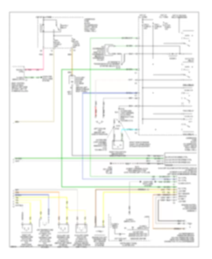
Manual A/C Wiring Diagram (2 of 2) for Saturn Relay 2007
List of elements for Manual A/C Wiring Diagram (2 of 2) for Saturn Relay 2007:
- (at engine to transmission stud nearest starter, below g113) g115
- (in forward lamp harness, 6 cm from breakout for c104 toward c110)
- (right side of engine compt on upper front of radiator support)
- 5v ref 1
- A/c cltch fuse 6 10a
- A/c cltch relay
- A/c compressor clutch (part of a/c compressor, behind a/c compressor pulley)
- A/c off for engine protection engine coolant hot
- A/c refrigerant pressure sensor (on high pressure hose, near high pressure hose connection to a/c compressor)
- Air temperature actuator (w/ front a/c) left air temperature actuator (w/ auxiliary a/c) (behind center of dash)
- Aux blwr motor speed ctrl
- Aux blwr motor speed sig
- Auxiliary air temperature actuator (w/ rear a/c) (behind left rear interior body panel)
- Auxiliary blower motor (w/ rear a/c) (behind left rear interior body panel)
- Auxiliary blower motor control module (w/ rear a/c) (in rear hvac module, behind left rear interior body panel)
- Auxiliary mode actuator (w/ rear a/c) (in rear hvac module, behind left rear interior body panel)
- Blwr motor speed ctrl
- Body control module (bcm) (below left side of dash, left of steering column)
- Class 2
- Class 2 data
- Class 2 serial data
- Computer data lines system
- Ctrl
- Diode 3
- Ect sensor
- Engine control module (ecm) (in air cleaner assembly)
- Engine coolant temperature (ect) sensor (top rear of engine)
- Fan 1 fuse 29 30a
- Fan 1 relay
- Fan 2 fuse 33 40a
- Fan 2 relay
- Fan 3 relay
- Frt/ blwr fuse 27 25a
- G100
- G401 (on lower left "d" pillar)
- Ground
- Hot at all times
- Hot coolant ind
- Hot w/ ign main relay energized
- Instrument panel cluster (ipc)
- Left cooling fan (behind left side of radiator)
- Logic
- Low ref
- Message center
- Pnk
- Red
- Right air temperature actuator (w/ auxiliary a/c) (right side hvac module)
- Right cooling fan (behind right side of radiator)
- Rly ctrl
- Rr blwr/ 110vac fuse 26 25a
- Run rly
- Run rly relay
- S102 (in forward lamp harness, 6.5 cm from breakout for g100, toward c110)
- S106
- S413 (in body harness, 6.5 cm from breakout for c479 toward left "c" pillar)
- Sens sig
- Serial data c1
- Tan
- Underhood fuse block (in underhood compt, above right front wheel well)

 Čeština
 Dansk
Dansk Deutsch
 Ελληνικά
 English
 Español
 Suomi
Suomi Français
 Français
 עברית
עברית Hrvatski
 Magyar
 Italiano
 日本語
日本語 한국어
한국어 Nederlands
 Polski
 Português
 Português
 Română
 Русский
 Slovenčina
 Slovenščina
 Svenska
 Türkçe
 中文 (中国)