ANTI-LOCK BRAKES
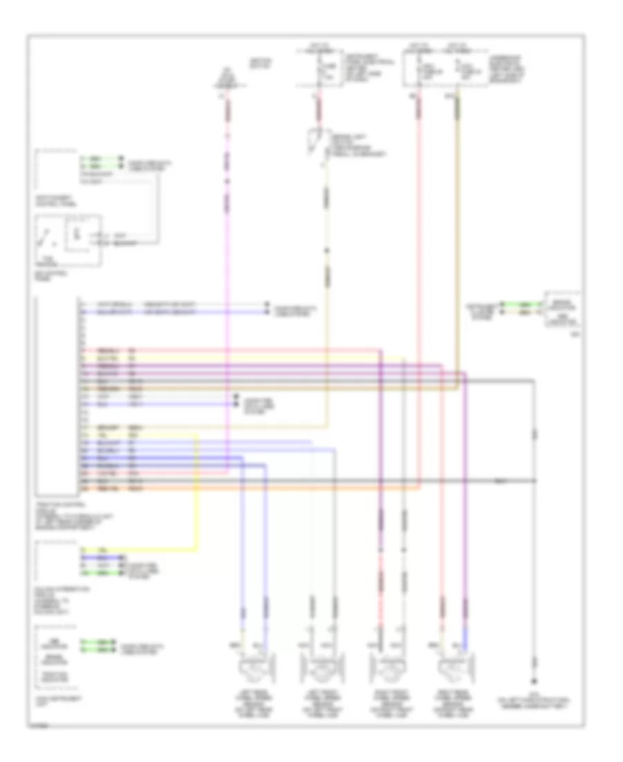
Anti-lock Brakes Wiring Diagram, with ESP for Saab 9-3 Aero 2006
 https://portal-diagnostov.com/license.html
Automotive Electricians Portal FZCO
Automotive Electricians Portal FZCO
https://portal-diagnostov.com/license.html
https://portal-diagnostov.com/license.html
Automotive Electricians Portal FZCO
Automotive Electricians Portal FZCO
List of elements for Anti-lock Brakes Wiring Diagram, with ESP for Saab 9-3 Aero 2006:
- 15+ on and start output
- Abs indicator
- Brake indicator
- Brake light switch (above brake pedal, on bracket)
- Column integration module (integral to steering column unit)
- Computer data lines system
- E65-2
- Esp control module (integral to hydraulic unit, at left rear corner of engine compartment)
- Esp switch
- Fuse 5a
- Fuse 7.5a
- G15 (on left-hand structural member under battery)
- G43 (behind right center of dash)
- Hot at all times
- Hs1-1
- Hs1-2(m/t) hs2-3(a/t)
- Hs2-1
- Hs2-2(m/t) hs1-3(a/t)
- Ignition switch
- Infotainment control panel
- Instrument cluster system
- Instrument panel electrical center (on left side of dash)
- Left front wheel speed sensor (on left front wheel hub)
- Left rear wheel speed sensor (on left rear wheel hub)
- Main instrument unit
- Maxi fuse 28 40a
- Maxi fuse 33 40a
- Nca
- R15
- R20
- R30-5
- R30-6
- R31-5
- R31-6
- Right front wheel speed sensor (on right front wheel hub)
- Right rear wheel speed sensor (on right rear wheel hub)
- Sid
- Sid control panel
- Steering angle sensor
- Traction indicator
- Underhood electrical center (uec) (left side of engine bay)
- Yaw sensor (below gear selector assembly)
Anti-lock Brakes Wiring Diagram, without ESP for Saab 9-3 Aero 2006
List of elements for Anti-lock Brakes Wiring Diagram, without ESP for Saab 9-3 Aero 2006:
- 15+ on & start output
- Abs indicator
- Brake indicator
- Brake light switch (above brake pedal, on bracket)
- Column integration module (integral to steering column unit)
- Computer data lines system
- E65-2
- Fuse 7.5a
- G15 (on left-hand structural member under battery)
- Hot at all times
- Hs1-1
- Hs1-2(m/t) hs2-3(a/t)
- Hs2-1
- Hs2-2(m/t) hs1-3(a/t)
- Ignition switch
- Infotainment control panel
- Instrument cluster system
- Instrument panel electrical center (on left side of dash)
- Left front wheel speed sensor (on left front wheel hub)
- Left rear wheel speed sensor (on left rear wheel hub)
- Main instrument unit
- Maxi fuse 28 40a
- Maxi fuse 33 40a
- Nca
- R15
- R20
- R30-5
- R30-6
- R31-5
- R31-6
- Right front wheel speed sensor (on right front wheel hub)
- Right rear wheel speed sensor (on right rear wheel hub)
- Sid
- Sid control panel
- Tcs switch
- Traction control module (integral to hydraulic unit, at left rear corner of engine compartment)
- Traction indicator
- Underhood electrical center (uec) (left side of engine bay)

 Čeština
 Dansk
Dansk Deutsch
 Ελληνικά
 English
 Español
 Suomi
Suomi Français
 Français
 עברית
עברית Hrvatski
 Magyar
 Italiano
 日本語
日本語 한국어
한국어 Nederlands
 Polski
 Português
 Português
 Română
 Русский
 Slovenčina
 Slovenščina
 Svenska
 Türkçe
 中文 (中国)