СИСТЕМА УПРАВЛЕНИЯ ДВИГАТЕЛЯ
2.0L ТУРБО
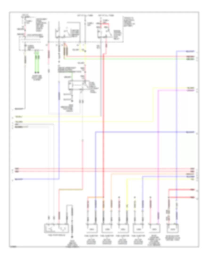
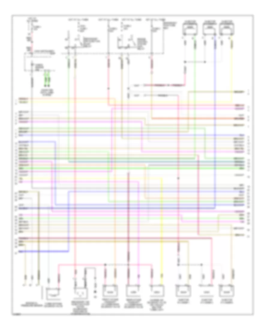
2.0L турбо, Электросхема системы управления двигателем (1 из 4) для Saab 9-3 2.0T 2006
 https://portal-diagnostov.com/license.html
Automotive Electricians Portal FZCO
Automotive Electricians Portal FZCO
https://portal-diagnostov.com/license.html
https://portal-diagnostov.com/license.html
Automotive Electricians Portal FZCO
Automotive Electricians Portal FZCO
2.0L турбо, Электросхема системы управления двигателем (1 из 4) для Saab 9-3 2.0T 2006 - Список элементов:
- A/c pressure sensor (near left front corner of air filter)
- A10-1
- Accelerator pedal position sensor (on pedal bracket)
- Air conditioning system
- Brake light switch (above brake pedal, on bracket)
- C10
- C31-20
- Computer data lines system
- Cruise control brake switch (on brake pedal bracket)
- Cruise control clutch switch (near top of clutch
- E11
- E15-29
- E15-5
- E201-1
- E30-17
- E30-18
- E30-19
- E30-35
- E31-11
- E31-12
- E31-13
- E31-21
- E31-30
- E31-7
- E64
- E65
- E66
- E67
- E68
- E69
- E70
- E71
- E71-6
- E72
- E73-1
- E74-1
- E75
- E77
- E84
- Engine oil level switch (left side of oil pan)
- Evap pressure sensor (on fuel tank by fuel pump)
- Fuse 2 10a
- Fuse 2 5a
- Fuse 21 7.5a
- Fuse 4 10a
- Fuse 6 7.5a
- G7 (above upper right engine control module attachment eye)
- Hot at all times
- Hot in on or start
- Hs1
- Hs2
- Ignition switch module
- Instrument panel electrical center (on left side of dash)
- M24
- Pedal)
- Power distribution system
- Power steering fluid pressure sensor (on top of servo pump)
- Red
- Starting/ charging system
- Starting/charging system
- Trionic control module (front of engine)
- Underhood electrical center (left side of engine bay)
- X+ off & on output
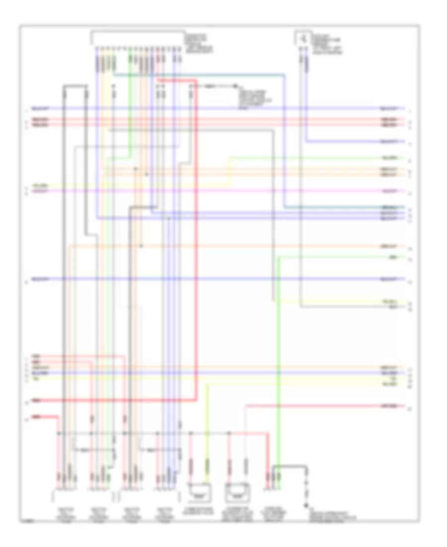
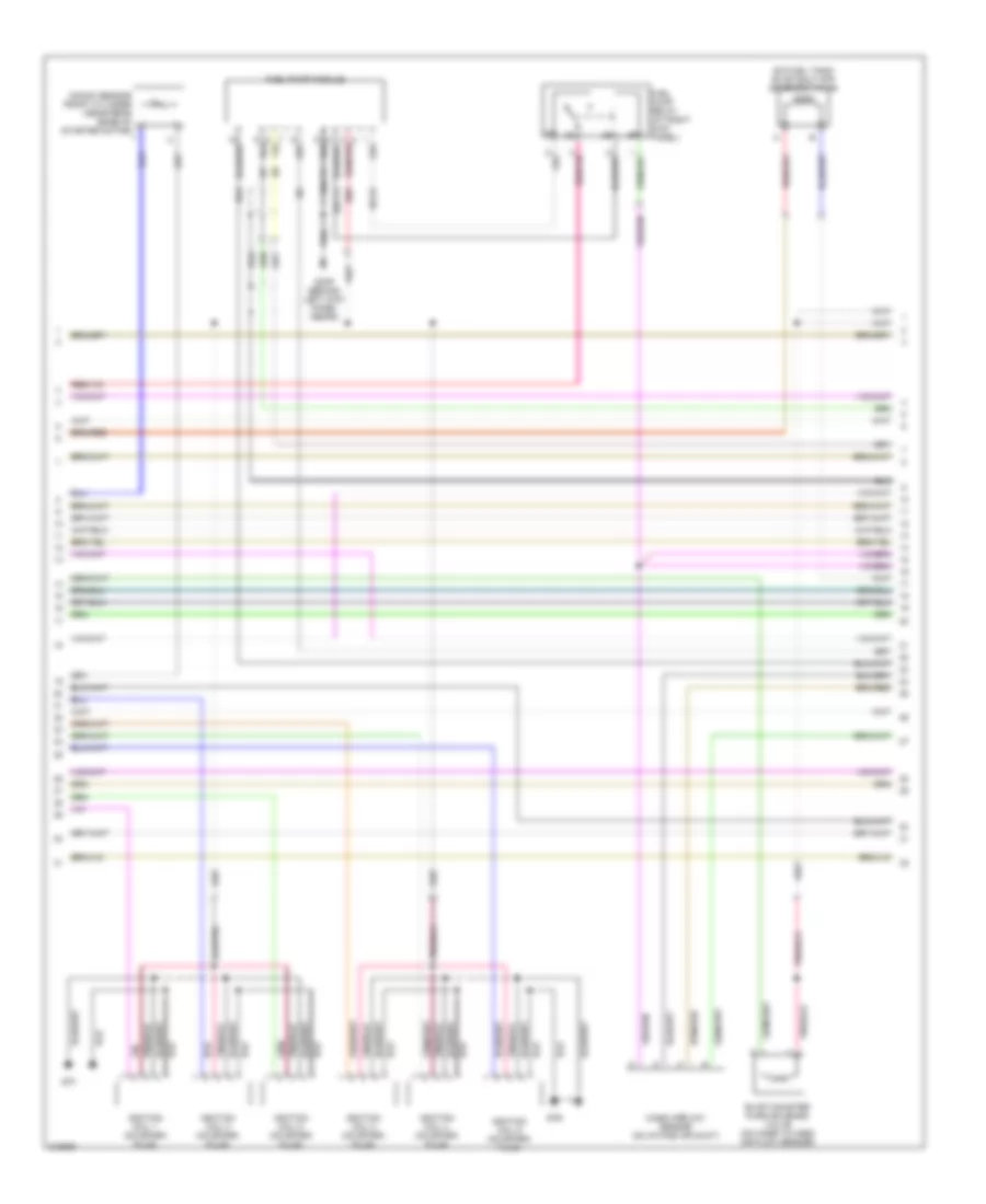
2.0L турбо, Электросхема системы управления двигателем (2 из 4) для Saab 9-3 2.0T 2006
2.0L турбо, Электросхема системы управления двигателем (2 из 4) для Saab 9-3 2.0T 2006 - Список элементов:
- Check engine ind
- Computer data lines system
- Engine control system main relay
- Evap canister purge valve (on hose to mass air flow sensor)
- Evap shut-off solenoid valve (on fuel tank)
- Fuel injector (on top of intake manifold)
- Fuel pump module
- Fuel pump relay (at right kick panel)
- Fuse 2 20a
- Fuse 4 10a
- Fuse 4 30a
- G34s (behind right kick panel (front))
- G7 (above upper right engine control module attachment eye)
- Heated oxygen sensor relay
- Hot at all times
- Instrument panel electrical center (on left side of dash)
- Main instrument
- Nca
- Red
- Trionic t8 electrical center (in front of battery)
- Unit
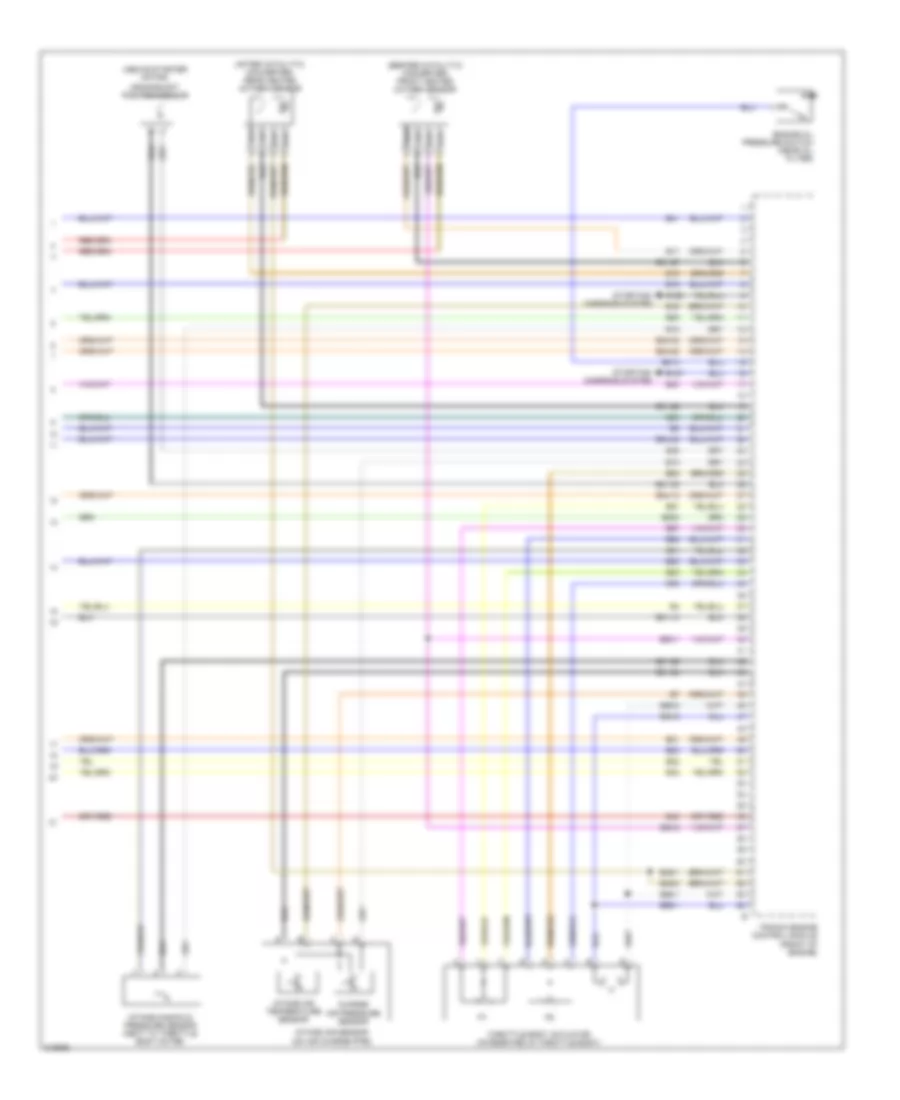
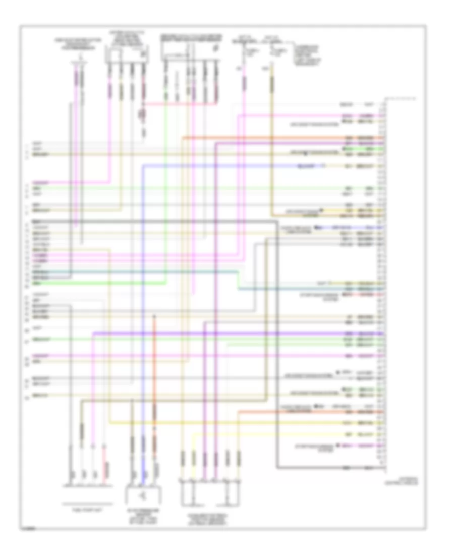
2.0L турбо, Электросхема системы управления двигателем (3 из 4) для Saab 9-3 2.0T 2006
2.0L турбо, Электросхема системы управления двигателем (3 из 4) для Saab 9-3 2.0T 2006 - Список элементов:
- Charge air solenoid valve (on vacuum box for turbo unit)
- Coolant temperature sensor (at front left side of engine)
- G7 (above upper right engine control module attachment eye)
- Ignition coil 1 (on spark plug)
- Ignition coil 2 (on spark plug)
- Ignition coil 3 (on spark plug)
- Ignition coil 4 (on spark plug)
- Ionization detection module (left rear of engine compt)
- Mass air- flow sensor (on intake air duct)
- Red
- Turbo bypass solenoid valve
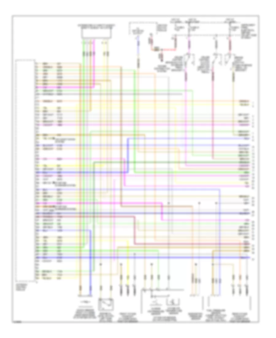
2.0L турбо, Электросхема системы управления двигателем (4 из 4) для Saab 9-3 2.0T 2006
2.0L турбо, Электросхема системы управления двигателем (4 из 4) для Saab 9-3 2.0T 2006 - Список элементов:
- (above starter motor)
- (after catalytic converter) rear heated oxygen sensor
- (before catalytic converter) front heated oxygen sensor
- Charge air pressure sensor
- Crankshaft position sensor
- E12
- E126
- E127
- E13
- E15
- E16
- E17
- E18
- E20
- E200
- E21
- E210
- E22
- E23
- E31-10
- E31-22
- E31-23
- E31-24
- E31-26
- E31-27
- E34-12
- E34-22
- E34-32
- E34-42
- E38
- E40
- E41
- E42
- E43
- E49-1
- E49-2
- E51
- E52
- E53
- E54
- E55-1
- E55-2
- E56-1
- E56-2
- E57
- E58
- E63
- E80-1
- E80-2
- E81
- E83
- Engine oil pressure switch (near oil filter)
- Intake air sensor (on air charge pipe)
- Intake air temperature sensor
- Intake manifold pressure sensor (next to throttle body motor)
- Starting/ charging system
- Throttle body actuator (integrated in throttle body)
- Trionic engine control module (front of engine)
2.8L ТУРБО
2.8L турбо, Электросхема системы управления двигателем (1 из 4) для Saab 9-3 2.0T 2006
2.8L турбо, Электросхема системы управления двигателем (1 из 4) для Saab 9-3 2.0T 2006 - Список элементов:
- (integrated in throttle body) throttle body actuator
- 470d
- 605e
- 705c
- Air conditioning system
- Barometric pressure sensor
- Brake light switch (above brake pedal, on bracket)
- Charge air pressure sensor
- Cruise control brake switch (on brake pedal bracket)
- Cruise control clutch switch (near top of clutch
- Engine oil level switch (left side of oil pan)
- Front intake camshaft cylinder bank position sensor
- Fuel pressure sensor (under induction pipe, on right end of fuel rail)
- Fuse 2 5a
- Fuse 21 7.5a
- Fuse 6 7.5a
- Hot at all times
- Hot in on or start
- Ignition switch module
- Instrument panel electrical center (on left side of dash)
- Intake air sensor (on air charge pipe)
- Intake air temperature sensor
- Knock sensor front cylinder (near rear edge of starter motor)
- Motronic control module
- Nca
- Pedal)
- Power distribution system
- Rear intake camshaft cylinder bank position sensor
- Starting/ charging system
- X+ off or on output
2.8L турбо, Электросхема системы управления двигателем (2 из 4) для Saab 9-3 2.0T 2006
2.8L турбо, Электросхема системы управления двигателем (2 из 4) для Saab 9-3 2.0T 2006 - Список элементов:
- Charge air solenoid valve (on vacuum box for turbo unit)
- Check engine ind
- Computer data lines system
- Engine bay main fuse box
- Engine control system main relay
- Engine oil pressure sensor
- Front intake camshaft cylinder bank solenoid valve
- Fuse 2 20a
- Fuse 3 20a
- Fuse 4 10a
- Fuse 4 30a
- Hot at all times
- Injector cylinder 1
- Injector cylinder 2
- Injector cylinder 3
- Injector cylinder 4
- Injector cylinder 5
- Injector cylinder 6
- Main instrument
- Maxi fuse 1 60a
- Nca
- Rear intake camshaft cylinder bank solenoid valve
- Red
- Secondary air injection pump motor (on bracket forward of starter motor)
- Secondary air injection pump relay
- Turbo bypass solenoid valve
- Unit
2.8L турбо, Электросхема системы управления двигателем (3 из 4) для Saab 9-3 2.0T 2006
2.8L турбо, Электросхема системы управления двигателем (3 из 4) для Saab 9-3 2.0T 2006 - Список элементов:
- (on fuel tank) evap shut-off solenoid valve
- E10
- E2-33
- E30
- E31-11
- E31-74
- Evap canister purg solenoid valve (on hose to mass air flow sensor)
- Fuel pump module
- Fuel pump relay (at right kick panel)
- G33p (behind left kick panel (rear))
- G7f
- G7r
- Ignition coil 1 (on spark plug)
- Ignition coil 2 (on spark plug)
- Ignition coil 3 (on spark plug)
- Ignition coil 4 (on spark plug)
- Ignition coil 5 (on spark plug)
- Ignition coil 6 (on spark plug)
- Knock sensor front cylinder (near rear edge of starter motor)
- Mass airflow sensor (on intake air duct)
2.8L турбо, Электросхема системы управления двигателем (4 из 4) для Saab 9-3 2.0T 2006
2.8L турбо, Электросхема системы управления двигателем (4 из 4) для Saab 9-3 2.0T 2006 - Список элементов:
- (above starter motor) crankshaft position sensor
- (after catalytic converter) rear heated oxygen sensor
- (before catalytic converter) front heated oxygen sensor
- (or hs1-2)
- (or hs2-2)
- A10-1
- Accelerator pedal position sensor (on pedal bracket)
- Air conditioning system
- C10
- C25
- C26
- C27
- C31-20
- Computer data lines system
- E11
- E15-4
- E150
- E201-1
- E30-15
- E30-35
- E30-7
- E31-1
- E41
- E48
- E63
- E64
- E65
- E66
- E67
- E68
- E69
- E70
- E71
- E72
- E74-1
- E75
- E76-1
- E89
- E90
- E91
- Evap pressure sensor (on fuel tank by fuel pump)
- Fuel pump unit
- Fuse 2 10a
- Fuse 4 10a
- Hot at all times
- Hot in on or start
- Hs1
- Hs2
- M24
- Motronic control module
- Nca
- Starting/charging system
- Underhood electrical center (left side of engine bay)

 Čeština
 Dansk
Dansk Deutsch
 Ελληνικά
 English
 Español
 Suomi
Suomi Français
 Français
 עברית
עברית Hrvatski
 Magyar
 Italiano
 日本語
日本語 한국어
한국어 Nederlands
 Polski
 Português
 Português
 Română
 Русский
 Slovenčina
 Slovenščina
 Svenska
 Türkçe
 中文 (中国)