AIR CONDITIONING
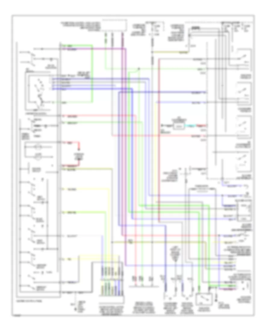
Heater Wiring Diagram for Acura Integra GS-R 2000
List of elements for Heater Wiring Diagram for Acura Integra GS-R 2000:
- (above left kick panel) g200
- Bi-lev switch
- Blower motor (behind glove box, on bottom of blower motor housing)
- Blower motor relay
- Blower resistor (behind glove box, on top of blower motor housing)
- C216
- C217
- C439
- Defrost switch
- Dimming circuit
- Fresh
- Fresh/ recirc switch
- Fuse 40a
- Fuse 7.5a
- G101 (right front corner of engine compartment)
- G200 (above left kick panel)
- Heat switch
- Heat/def switch
- Heater control panel
- Heater fan switch
- Hot at all times
- Hot in on
- Illum
- Interior lights system
- Mode control motor (behind left side of dash, on left side of heater assembly)
- Off
- Recirc
- Recirculate
- Recirculation control motor (behind glove box, on rear left side of blower housing)
- Red
- Underdash fuse/relay box (under left side of dash)
- Underhood fuse/relay box (right rear corner of engine compartment, near battery)
- Vent switch
Manual A/C Wiring Diagram for Acura Integra GS-R 2000
List of elements for Manual A/C Wiring Diagram for Acura Integra GS-R 2000:
- (above left kick panel) g200
- (behind glove box)
- (behind glove box, on rear left side of blower housing)
- (left front of engine compart -ment) g100
- (on bracket)
- A/c compressor clutch
- A/c compressor clutch relay
- A/c diode (above right kick panel)
- A/c on indicator
- A/c pressure switch (in refrig pipe, between receiver-driver & condenser)
- A/c switch
- A/c thermostat (in evap housing, on evaporator core)
- Bi-lev switch
- Blower motor
- Blower motor relay
- Blower resistor
- C215
- C216
- C217
- C439
- Compartment)
- Condenser fan motor (behind left side of radiator)
- Condenser fan relay
- Defrost switch
- Dimming circuit
- Diode
- Fresh
- Fresh/ recirc switch
- Fuse 20a
- Fuse 40a
- Fuse 7.5a
- G101 (right front corner of engine
- G112 (left side of engine)
- Heat switch
- Heat/def switch
- Heater control panel
- Heater fan switch
- High
- Hot at all times
- Hot in on underdash fuse/relay box (under left side of dash)
- Illum
- Interior lights system
- Low
- Mode control motor (behind left side of dash, on left side of heater assembly)
- Nca
- Off
- Powertrain control module (pcm) or engine control module (ecm) (behind right side kick panel)
- Radiator fan motor (behind right side of radiator)
- Radiator fan relay
- Radiator fan switch
- Recirc
- Recirculation control motor
- Red
- Thermistor
- Underhood fuse/relay box (right rear corner of engine compt, near battery)
- Vent switch

 Čeština
 Dansk
Dansk Deutsch
 Ελληνικά
 English
 Español
 Suomi
Suomi Français
 Français
 עברית
עברית Hrvatski
 Magyar
 Italiano
 日本語
日本語 한국어
한국어 Nederlands
 Polski
 Português
 Português
 Română
 Русский
 Slovenčina
 Slovenščina
 Svenska
 Türkçe
 中文 (中国)