AIR CONDITIONING
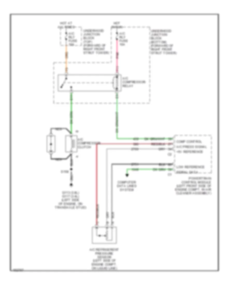
Compressor Wiring Diagram for Chevrolet Impala 2002
List of elements for Compressor Wiring Diagram for Chevrolet Impala 2002:
- +5v reference
- A/c compressor clutch
- A/c compressor relay
- A/c press signal
- A/c refrigerent pressure sensor (left side of engine compt, on liquid line)
- A/c rly fuse 10a
- Comp control
- Computer data lines system
- E11
- F11
- G113 (3.8l) g117 (3.4l) (left side of engine, on transaxle stud)
- Hot at all times
- Hot in run
- Low reference
- Nca
- Pnk
- Powertrain control module (left front side of engine compt, in air cleaner assembly)
- S158
- Serial data
- Underhood junction block (bottom) (forward of right front strut tower)
- Underhood junction block (top) (forward of right front strut tower)
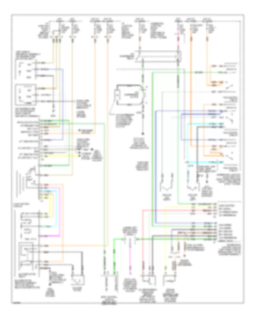
Manual A/C Wiring Diagram for Chevrolet Impala 2002
List of elements for Manual A/C Wiring Diagram for Chevrolet Impala 2002:
- (dash harn, 6 cm from hvac module breakout)
- (dash harn, 8 cm from ignition sw breakout) s229
- (forward lamp harn, near left headlamp)
- (forward lamp harn, near right headlamp)
- (fuel inj harn, near breakout to map sensor)
- (left side of heater-a/c assembly) air temperature actuator (left)
- (under center of dash)
- (under left side of dash) splice pack sp205
- +5v reference
- 3.4l
- 3.8l
- A/c blo fuse 20a
- A/c blo fuse 25a
- A/c compressor clutch
- A/c compressor clutch diode (in wiring harn, 10 cm from a/c compressor clutch)
- A/c compressor relay
- A/c cruise fuse 10a
- A/c press signal
- A/c refrigerent pressure sensor (left side of engine compt, on liquid line)
- A/c request
- A/c request sig
- A/c rly fuse 10a
- Air temperature actuator (right) (right side of heater-a/c assembly)
- B10
- Battery
- Blower motor
- Blower motor relay
- Blower motor resistor assembly (on hvac module, below blower motor)
- Body control module (behind left side of dash)
- C1 f6
- C10
- Comp control
- Cooling fan (left)
- Cooling fan (right)
- D4 c1
- Data link connector (under dash, right side of steering column)
- Defog rly ctrl
- Defogger system
- Dic/ rke fuse 10a
- E11
- Ect ground
- Ect signal
- Engine controls (map sensor)
- Engine coolant temperature (ect) sensor (left rear of engine)
- F11
- F5 c1
- Fan cont 1 fuse 25a
- Fan cont 2 & 3 fuse 25a
- Fan control 1 relay
- Fan control 2 relay
- Fan control 3 relay
- G101 (top left front of radiator support)
- G113 (3.8l) g117 (3.4l) (left side of engine, on transaxle stud)
- G201 (right side of steering column)
- G202
- G202 (under center of dash)
- Gnd
- High speed
- Hot at all times
- Hot in run
- Hvac control module
- I/p junction block (left) (behind left side of dash)
- I/p junction block (right) (behind right side of dash)
- I/p lamp sply volt
- Ign
- Ign 3 volt
- Interior lights system
- Lft temp dr ctrl
- Low reference
- Low speed
- Nca
- Nca nca
- Off
- Off blwr mtr ctrl
- Pnk
- Pos
- Powertrain control module (left front side of engine compt, in air cleaner assembly)
- Rt temp dr ctrl
- S121
- S148
- S158
- S175
- S216
- Serial data
- Tan
- Underhood junction block (bottom) (right side of engine compt, forward of strut tower)
- Underhood junction block (top) (forward of right front strut tower)

 Čeština
 Dansk
Dansk Deutsch
 Ελληνικά
 English
 Español
 Suomi
Suomi Français
 Français
 עברית
עברית Hrvatski
 Magyar
 Italiano
 日本語
日本語 한국어
한국어 Nederlands
 Polski
 Português
 Português
 Română
 Русский
 Slovenčina
 Slovenščina
 Svenska
 Türkçe
 中文 (中国)