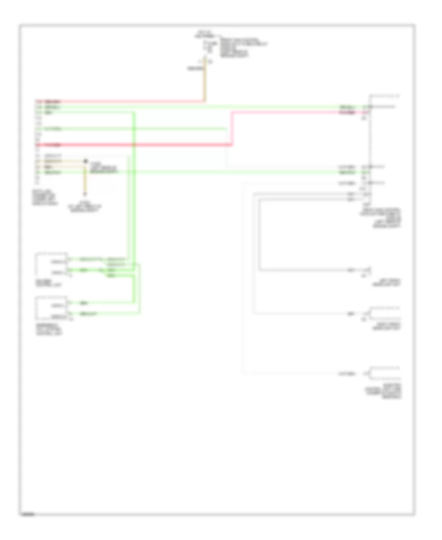
COMPUTER DATA LINES
Data Link Connector Wiring Diagram for Mercedes-Benz CLK350 2007
List of elements for Data Link Connector Wiring Diagram for Mercedes-Benz CLK350 2007:
- C10
- C24
- Can-c h
- Can-c l
- Data link connector (under left side of dash)
- Eis (ezs) control unit
- Electric control unit (vgs) (under automatic gear box)
- Emergency call system control unit
- Front sam control module fuse & relay module (left rear of engine compt)
- Front sam control module w/ fuse & relay module (left rear of engine compt)
- Fuse 5a
- Hot at all times
- Left front headlamp unit
- Pnk/red
- Right front headlamp unit
- W16/3 (at left front of engine compt)
- W16/5 (left rear of engine compt)
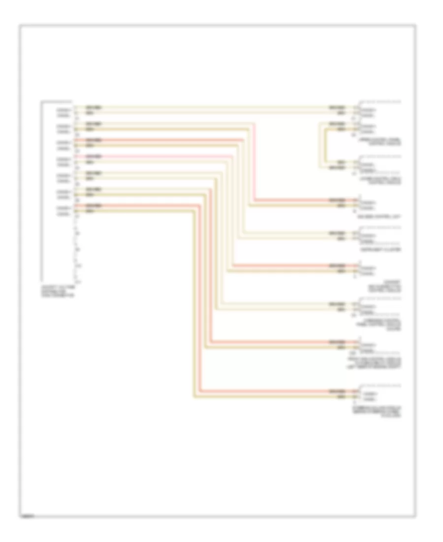
High/Low Bus Wiring Diagram (1 of 3) for Mercedes-Benz CLK350 2007
List of elements for High/Low Bus Wiring Diagram (1 of 3) for Mercedes-Benz CLK350 2007:
- C10
- C11
- C20
- Can-b h
- Can-b h
- Can-b l
- Cockpit voltage distributor (can) connector
- Comfort aac pushbutton control module
- Eis (ezs) control unit
- Front sam control module w/ fuse & relay module (left rear of engine compt)
- Instrument cluster
- Lower control field control module
- Overhead control panel control module (coupe)
- Steering column module (behind steering wheel, in column)
- Upper control panel control module
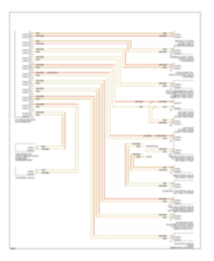
High/Low Bus Wiring Diagram (2 of 3) for Mercedes-Benz CLK350 2007
List of elements for High/Low Bus Wiring Diagram (2 of 3) for Mercedes-Benz CLK350 2007:
- C10
- C11
- C18
- Can-b h
- Can-b l
- Comand operating, display & control module (if equipped)
- Convertible
- Coupe
- Driver front seat adjustment control module w/ memory & easy entry (under driver's seat)
- Front passenger front seat adjustment control module w/memory & easy entry (under right front seat)
- Front sam control module w/ fuse & relay module (left rear of engine compt)
- Left front door control module (in left front door)
- Overhead control panel control module (convertible)
- Power soft top control module (left front of trunk)
- Pts control module (coupe) (behind right kick panel)
- Rear control module (left side of trunk)
- Rear sam control module w/ fuse & relay module (left side of trunk)
- Restraint systems control module (in center console)
- Right door control module (in right front door)
- Tpm control module
- Voltage distributor (can) connector
- Wss control unit (weight sensing system) (under front passenger's seat)
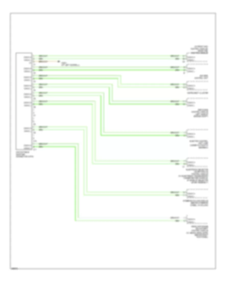
High/Low Bus Wiring Diagram (3 of 3) for Mercedes-Benz CLK350 2007
List of elements for High/Low Bus Wiring Diagram (3 of 3) for Mercedes-Benz CLK350 2007:
- (in front sam control module) me-sfi (me) control module
- C10
- C11
- Can databus adapter connector (2-pin)
- Can-c h
- Can-c l
- Eis (ezs) control unit
- Electric control unit (vgs) (under automatic gearbox)
- Electronic selector lever module control module (w/ electronic transmission) (under center console, at base of selector lever assembly)
- Esp & bas control module (left side of engine compt)
- Headlamp range adjustment control module (w/ xenon headlamps) (behind right kick panel)
- Instrument cluster
- Steering column module (behind steering wheel, in column)
- W28/1 (at left doorsill)

 Čeština
 Dansk
Dansk Deutsch
 Ελληνικά
 English
 Español
 Suomi
Suomi Français
 Français
 עברית
עברית Hrvatski
 Magyar
 Italiano
 日本語
日本語 한국어
한국어 Nederlands
 Polski
 Português
 Português
 Română
 Русский
 Slovenčina
 Slovenščina
 Svenska
 Türkçe
 中文 (中国)