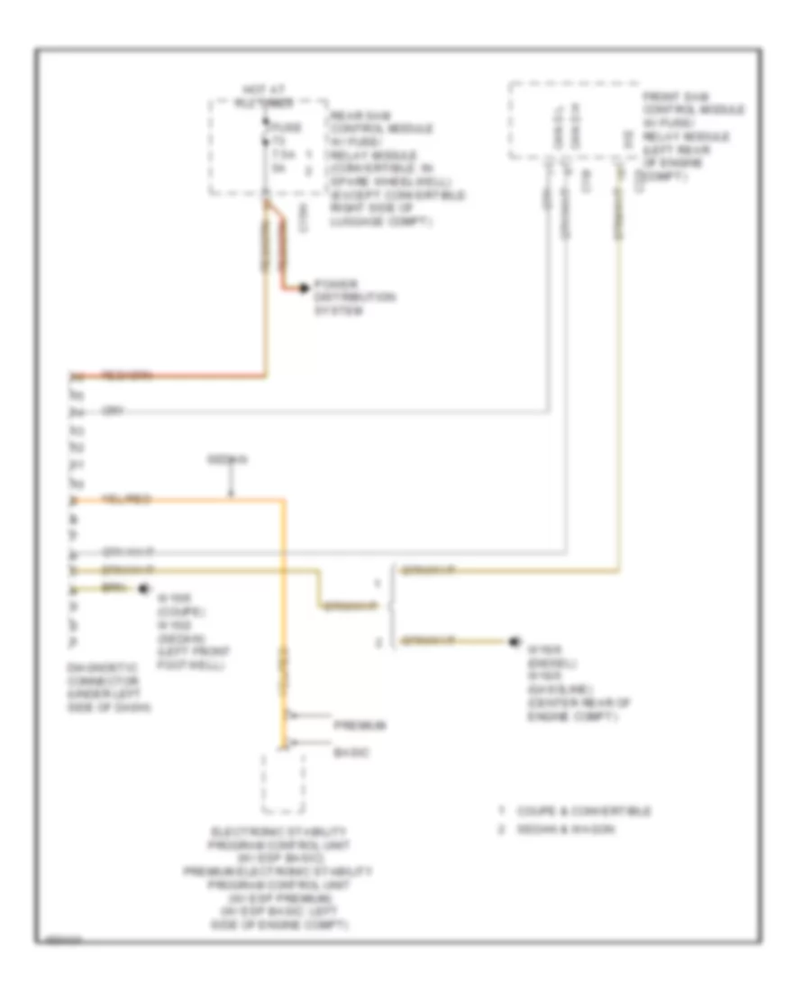
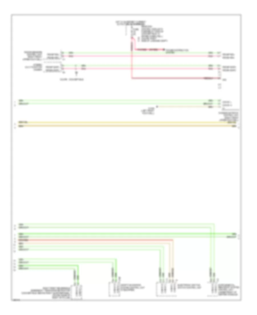
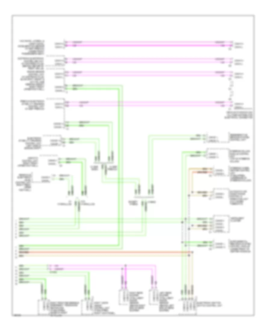
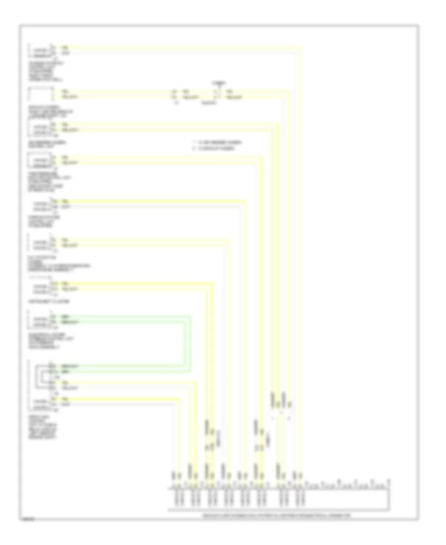
COMPUTER DATA LINES
Data Link Connector Wiring Diagram for Mercedes-Benz E350 2014
List of elements for Data Link Connector Wiring Diagram for Mercedes-Benz E350 2014:
- 31e
- Basic
- C15h
- C19i
- C22i
- Can d h
- Can d l
- Coupe & convertible
- Diagnostic connector (under left side of dash)
- Electronic stability program control unit (w/ esp basic) premium electronic stability program control unit (w/ esp premium) (w/ esp basic: left side of engine compt)
- Front sam control module w/ fuse/ relay module (left rear of engine compt)
- Fuse 7.5a 5a
- Hot at all times
- Power distribution system
- Premium
- Rear sam control module w/ fuse/ relay module (convertible: in spare wheelwell) (except convertible: right side of luggage compt)
- Sedan
- Sedan & wagon
- W15/5 (coupe) w15/2 (sedan) (left front footwell)
- W16/6 (diesel) w16/5 (gasoline) (center rear of engine compt)
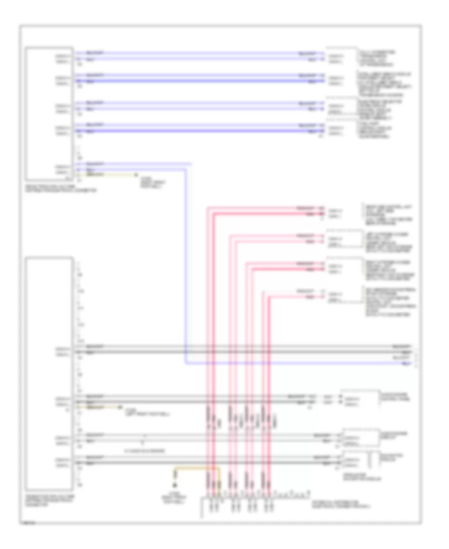
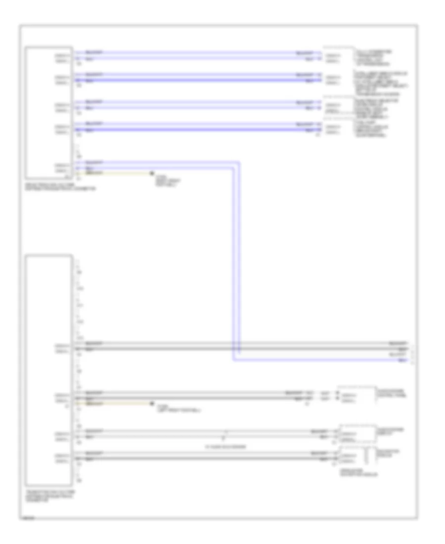
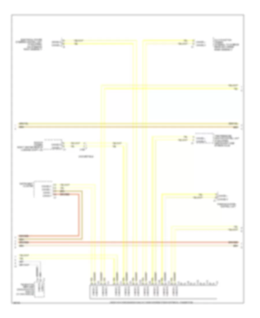
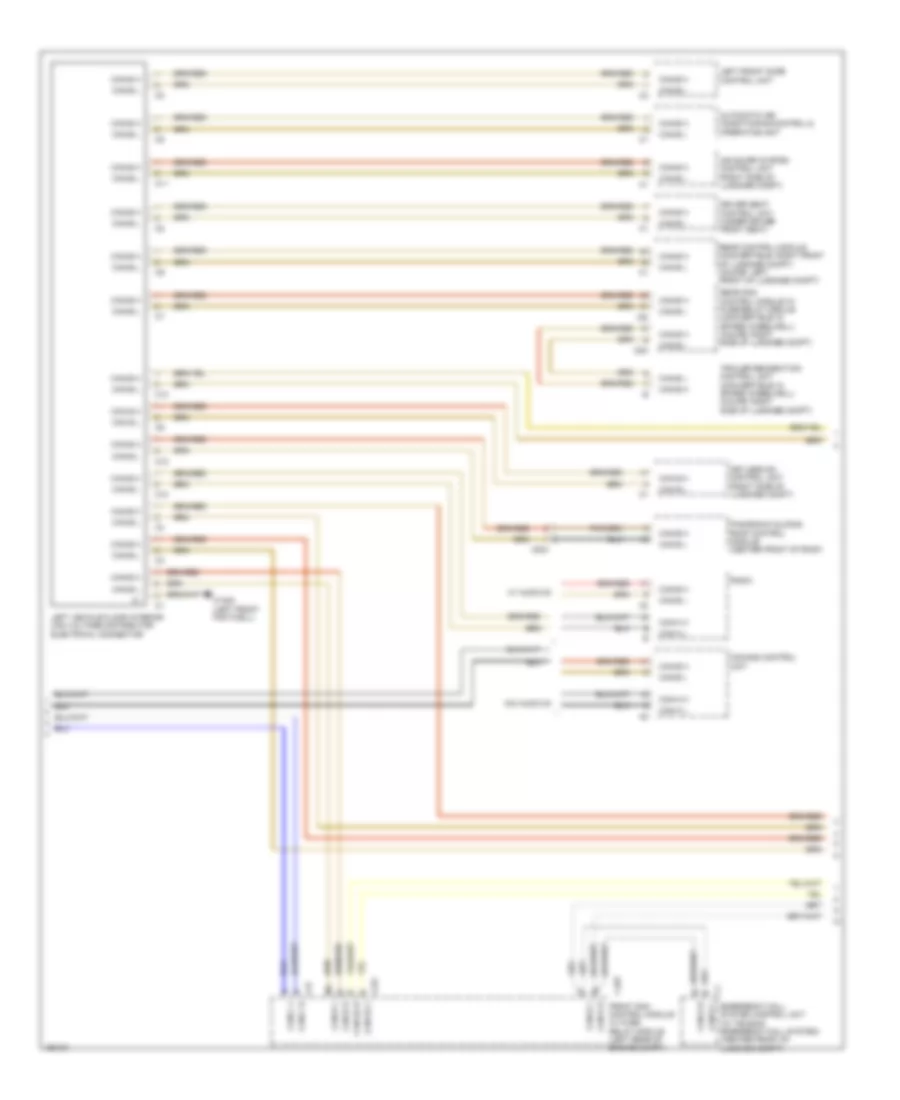
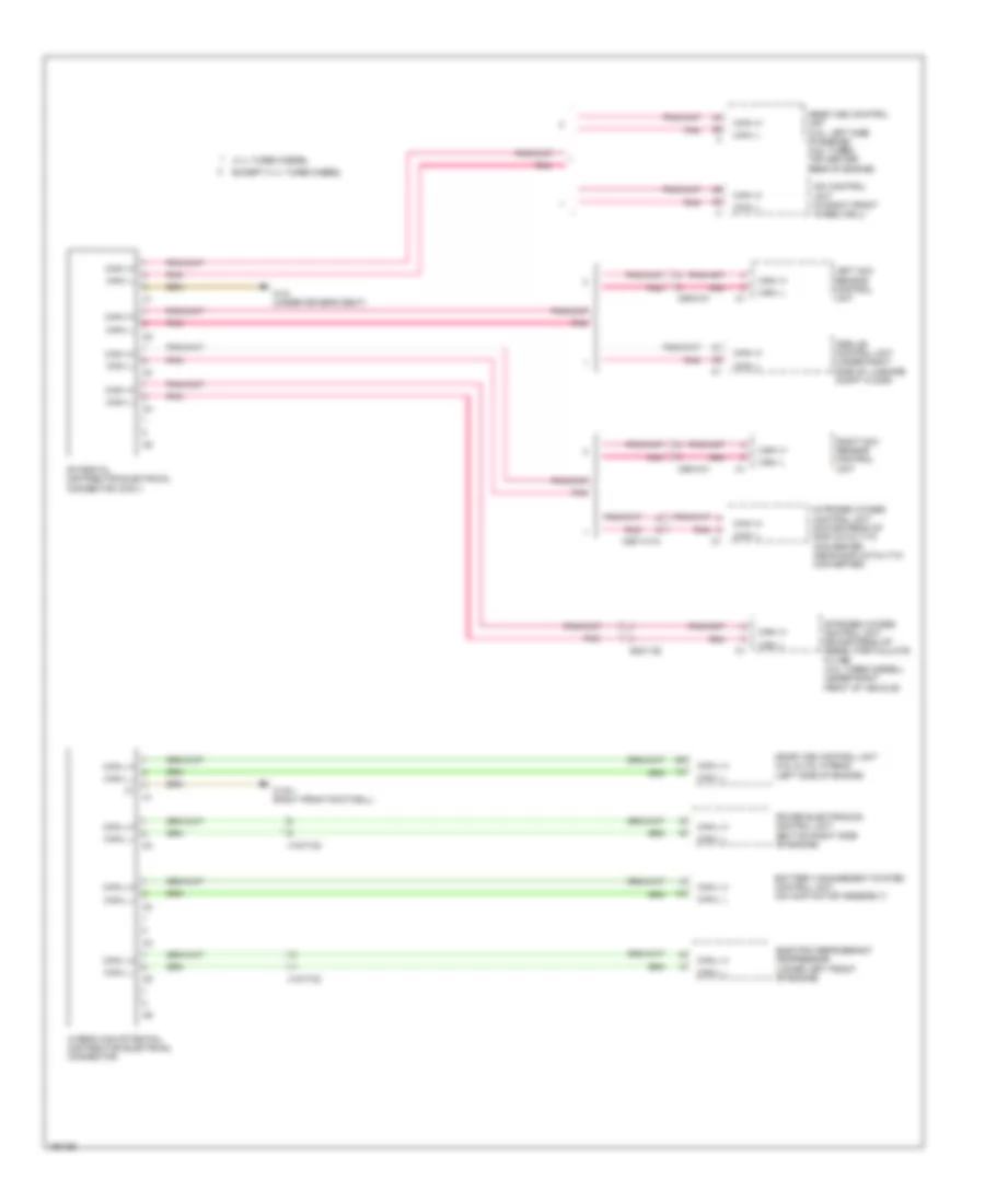
High/Low Bus Wiring Diagram, Convertible with CAN E1 (1 of 5) for Mercedes-Benz E350 2014
List of elements for High/Low Bus Wiring Diagram, Convertible with CAN E1 (1 of 5) for Mercedes-Benz E350 2014:
- Audio/comand control panel
- Audio/comand display
- C10
- C11
- C12
- C13
- Can i h
- Can i l
- Can-a h
- Can-a l
- Can-c h
- Can-c l
- Can-i h
- Can-i l
- Cradle for navigation module
- Drive train can voltage distributor electrical connector
- Electronic selector lever module control module (base of shift lever assembly)
- Fuel pump control module (behind right quarterpanel)
- Fully integrated transmission control unit (in transmission)
- Intelligent servo module for direct select (w/ intelligent servo module for direct select) (bottom of transmission housing)
- Left nitrogen oxides control unit (under vehicle, near left nox storage catalytic converter)
- Me-sfi [me] control unit (3.5l: left side of engine) (4.6l turbo: top center rear of engine)
- Navigation module
- Nox sensor downstream of nox storage catalytic converter control unit (in exhaust, downstream of scr catalytic converter)
- Pnk
- Potential distributor electrical connector (can i)
- Right nitrogen oxides control unit (under vehicle, near right nox storage catalytic converter)
- Telematics can voltage distributor electrical connector
- W/ audio 20 & comand
- W15/6 (left front footwell)
- W15/8 (right front footwell)
- X35/6
- X86/3-c1
- X86/4-c2
- X86/6-c1
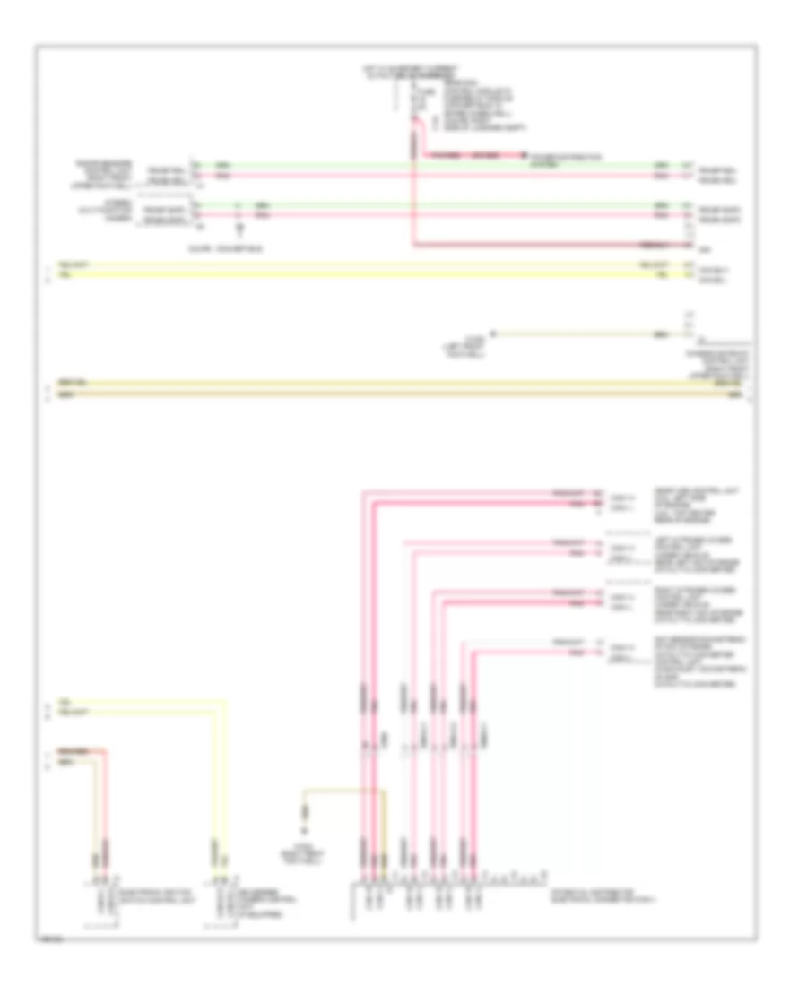
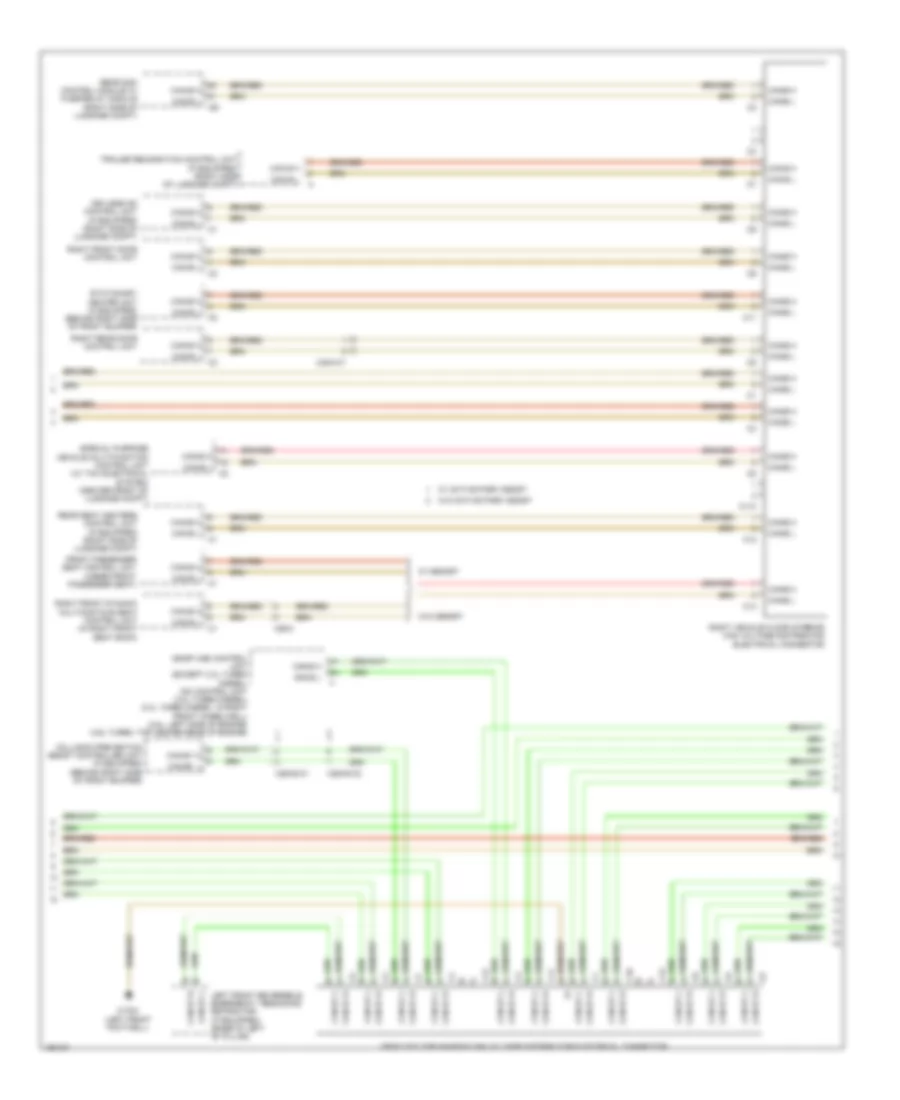
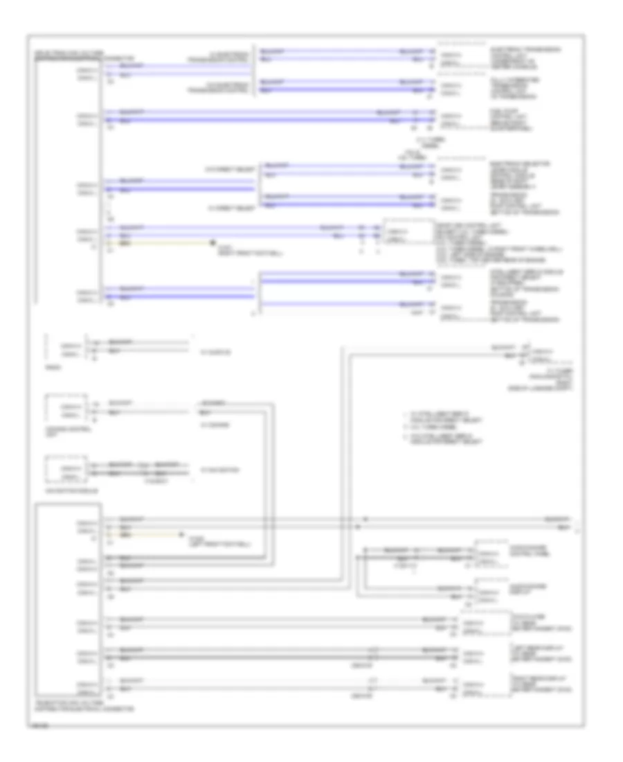
High/Low Bus Wiring Diagram, Convertible with CAN E1 (2 of 5) for Mercedes-Benz E350 2014
List of elements for High/Low Bus Wiring Diagram, Convertible with CAN E1 (2 of 5) for Mercedes-Benz E350 2014:
- Air scarf system control unit (right side of luggage compt)
- Automatic air conditioning control & operating unit
- C10
- C10t
- C11
- C12
- C13
- C19i
- C22i
- C2i
- C5h
- C9i
- Can b h
- Can b l
- Can bh
- Can-a h
- Can-a l
- Can-b h
- Can-b l
- Can-c h
- Can-c l
- Can-d h
- Can-d l
- Can-e1 h
- Can-e1 l
- Can-g h
- Can-g l
- Canb l
- Comand control unit
- Driver seat control unit (under driver front seat)
- Emergency call system control unit (w/ teleaid emergency call system) (center front of luggage compt)
- Front sam control module w/ fuse/ relay module (left rear of engine compt)
- Keyless go control unit (right side of luggage compt)
- Left front door control unit
- Left rear bumper intelligent radar sensor (early production) (behind left end of rear bumper)
- Left vehicle floor interior can voltage distributor electrical connector
- Panoramic sliding roof control module (center front of roof)
- Pnk
- Radio
- Rear control module (convertible: right front of luggage compt) (coupe: left front of luggage compt)
- Rear sam control module w/ fuse/relay module (convertible: in spare wheelwell) (coupe: right side of luggage compt)
- Right rear bumper intelligent radar sensor (early production) (behind right end of rear bumper)
- Trailer recognition control unit (convertible: in spare wheelwell) (coupe: right side of luggage compt)
- W/ audio 20
- W/o audio 20
- W15/6 (left front footwell)
- X204
- X35/28
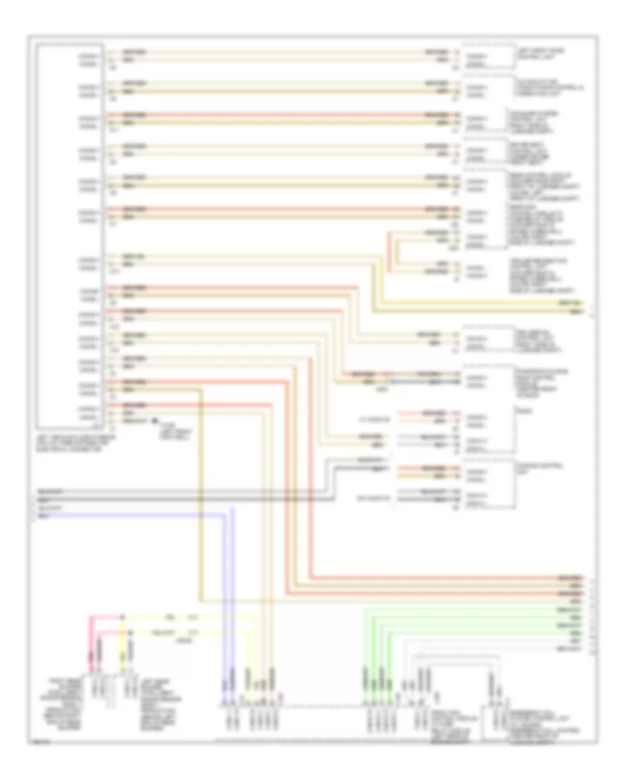
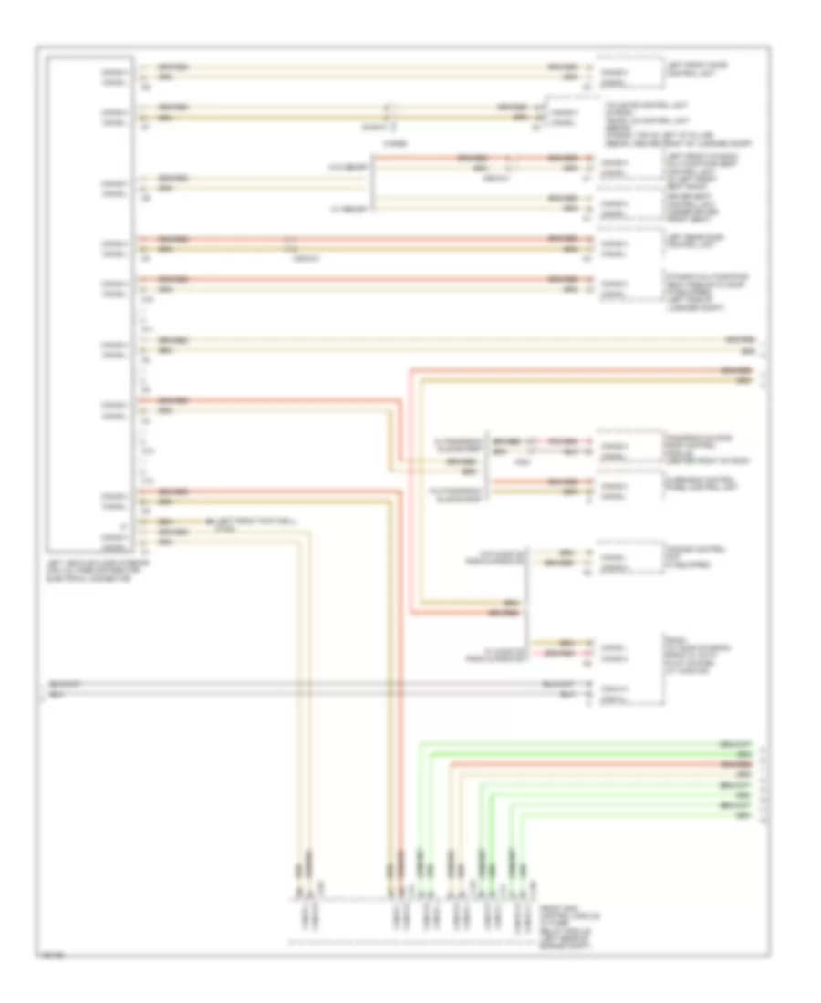
High/Low Bus Wiring Diagram, Convertible with CAN E1 (3 of 5) for Mercedes-Benz E350 2014
List of elements for High/Low Bus Wiring Diagram, Convertible with CAN E1 (3 of 5) for Mercedes-Benz E350 2014:
- C10
- C11
- C12
- C13
- Can-b h
- Can-b l
- Can-d h
- Can-d l
- Can-e1 h
- Can-e1 l
- Collision prevention assist controller unit (if equipped) (behind right side of front bumper)
- Instrument cluster
- Left front reversible emergency tensioning retractor (if equipped) (coupe: base of left front "b" pillar) (convertible: behind left quarterpanel)
- Left rear bumper intelligent radar sensor (late production) (behind left end of rear bumper)
- Right rear bumper intelligent radar sensor (late production) (behind right end of rear bumper)
- Steering column module control unit (top of steering column)
- Telematics services communication module (w/ com module)
- Vehicle floor chassis can e1 voltage distributor electrical connector
- W15/6 (left front footwell)
- X26/38
- X35/28-c2
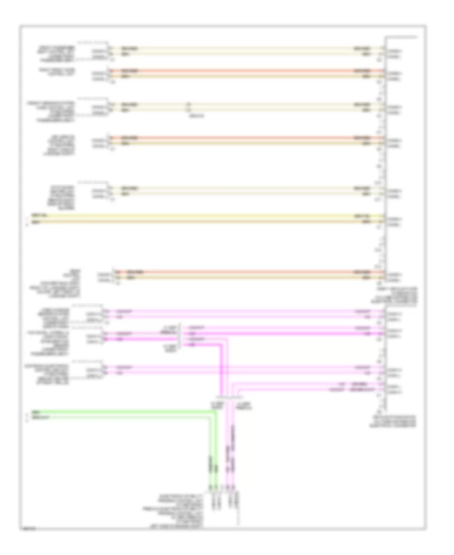
High/Low Bus Wiring Diagram, Convertible with CAN E1 (4 of 5) for Mercedes-Benz E350 2014
List of elements for High/Low Bus Wiring Diagram, Convertible with CAN E1 (4 of 5) for Mercedes-Benz E350 2014:
- (or red)
- 30g
- Adaptive damping system control unit (if equipped)
- C14i
- Can
- Can e1 h
- Can e1 l
- Can-b h
- Can-b l
- Can-e1 h
- Can-e1 l
- Chassis gateway control unit (right front upper footwell)
- Convertible
- Coupe
- Electronic ignition switch control unit
- Fr2-bm smpc
- Fr2-bp smpc
- Fr3-bm rdu
- Fr3-bp rdu
- Fuse 5a
- Hot w/ quiescent current cutout relay energized
- Pnk
- Pnk/red
- Power distribution system
- Radar sensors control unit (right front upper footwell)
- Rear sam control module w/ fuse/relay module (convertible: in spare wheelwell) (coupe: right side of luggage compt)
- Right front reversible emergency tensioning retractor (convertible: behind right quarterpanel) (coupe: base of right "b" pillar)
- Stereo multi-function camera
- W15/6 (left front footwell)
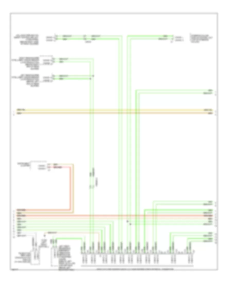
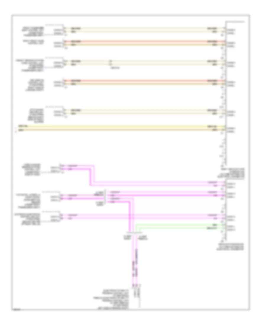
High/Low Bus Wiring Diagram, Convertible with CAN E1 (5 of 5) for Mercedes-Benz E350 2014
List of elements for High/Low Bus Wiring Diagram, Convertible with CAN E1 (5 of 5) for Mercedes-Benz E350 2014:
- C10
- C11
- C12
- C13
- Can-b h
- Can-b l
- Can-e1 h
- Can-e1 l
- Can-h h
- Can-h l
- Distronic electronic controller unit (if equipped) (behind center of front grille)
- Electronic stability program control unit (w/ esp basic) premium electronic stability program control unit (w/ esp premium) (w/ esp basic: left side of engine compt)
- Front passenger seat control unit (under front passenger seat)
- Keyless go control unit (if equipped) (right side of luggage compt)
- Rear control unit (convertible: right front of luggage compt) (coupe: left front of luggage compt)
- Right front door control unit
- Right vehicle floor interior can voltage distributor electrical connector
- Stationary heater unit (if equipped) (behind right side of front bumper)
- Vehicle dynamics can voltage distributor electrical connector
- Video & radar sensor system control unit (under right side of dash)
- W/ esp basic
- W/ esp premium
- Weight sensing system (wss) control unit (if equipped) (under front passenger's seat)
- X55/4-c2
- Yaw rate, lateral & longitudinal acceleration sensor (under front passenger's seat)
High/Low Bus Wiring Diagram, Convertible without CAN E1 (1 of 5) for Mercedes-Benz E350 2014
List of elements for High/Low Bus Wiring Diagram, Convertible without CAN E1 (1 of 5) for Mercedes-Benz E350 2014:
- Audio/comand control panel
- Audio/comand display
- C10
- C11
- C12
- C13
- Can-a h
- Can-a l
- Can-c h
- Can-c l
- Cradle for navigation module
- Drive train can voltage distributor electrical connector
- Electronic selector lever module control module (base of shift lever assembly)
- Fuel pump control module (behind right quarterpanel)
- Fully integrated transmission control unit (in transmission)
- Intelligent servo module for direct select (w/ intelligent servo module for direct select) (bottom of transmission housing)
- Navigation module
- Telematics can voltage distributor electrical connector
- W/ audio 20 & comand
- W15/6 (left front footwell)
- W15/8 (right front footwell)
High/Low Bus Wiring Diagram, Convertible without CAN E1 (2 of 5) for Mercedes-Benz E350 2014
List of elements for High/Low Bus Wiring Diagram, Convertible without CAN E1 (2 of 5) for Mercedes-Benz E350 2014:
- Air scarf system control unit (right side of luggage compt)
- Automatic air conditioning control & operating unit
- C10
- C10t
- C11
- C12
- C13
- C22i
- C2i
- C5h
- C9i
- Can b h
- Can b l
- Can-a h
- Can-a l
- Can-b h
- Can-b l
- Can-c h
- Can-c l
- Can-d h
- Can-d l
- Can-e2 h
- Can-e2 l
- Comand control unit
- Driver seat control unit (under driver front seat)
- Emergency call system control unit (w/ teleaid emergency call system) (center front of luggage compt)
- Front sam control module w/ fuse/ relay module (left rear of engine compt)
- Keyless go control unit (right side of luggage compt)
- Left front door control unit
- Left vehicle floor interior can voltage distributor electrical connector
- Panoramic sliding roof control module (center front of roof)
- Radio
- Rear control module (convertible: right front of luggage compt) (coupe: left front of luggage compt)
- Rear sam control module w/ fuse/relay module (convertible: in spare wheelwell) (coupe: right side of luggage compt)
- Trailer recognition control unit (convertible: in spare wheelwell) (coupe: right side of luggage compt)
- W/ audio 20
- W/o audio 20
- W15/6 (left front footwell)
- X204
High/Low Bus Wiring Diagram, Convertible without CAN E1 (3 of 5) for Mercedes-Benz E350 2014
List of elements for High/Low Bus Wiring Diagram, Convertible without CAN E1 (3 of 5) for Mercedes-Benz E350 2014:
- Backup camera (right center rear of luggage compt lid)
- C10
- C11
- C12
- C13
- Can-b h
- Can-b l
- Can-d h
- Can-d l
- Can-e2 h
- Can-e2 l
- Convertible
- Electrical power steering control unit (if equipped) (on steering rack assembly)
- Instrument cluster
- Multi-function camera (integral to interior rearview mirror base assembly)
- Parking system control unit
- Telematics services communication module (w/ com module)
- Tire pressure monitor control unit (if equipped) (above right side of rear axle)
- Vehicle floor chassis can voltage distributor electrical connector
- X169
High/Low Bus Wiring Diagram, Convertible without CAN E1 (4 of 5) for Mercedes-Benz E350 2014
List of elements for High/Low Bus Wiring Diagram, Convertible without CAN E1 (4 of 5) for Mercedes-Benz E350 2014:
- (or red)
- 30g
- 360 degree camera control unit (if equipped)
- C14i
- Can e2 h
- Can e2 l
- Can i h
- Can i l
- Can-b h
- Can-b l
- Can-e2 h
- Can-e2 l
- Can-i h
- Can-i l
- Chassis gateway control unit (right front upper footwell)
- Convertible
- Coupe
- Electronic ignition switch control unit
- Fr2-bm smpc
- Fr2-bp smpc
- Fr3-bm rdu
- Fr3-bp rdu
- Fuse 5a
- Hot w/ quiescent current cutout relay energized
- Left nitrogen oxides control unit (under vehicle, near left nox storage catalytic converter)
- Me-sfi (me) control unit (3.5l: left side of engine) (4.6l: top center rear of engine)
- Nox sensor downstream of nox storage catalytic converter control unit (in exhaust, downstream of scr catalytic converter)
- Pnk
- Pnk/red
- Potential distributor electrical connector (can i)
- Power distribution system
- Radar sensors control unit (right front upper footwell)
- Rear sam control module w/ fuse/relay module (convertible: in spare wheelwell) (coupe: right side of luggage compt)
- Right nitrogen oxides control unit (under vehicle, near right nox storage catalytic converter)
- Stereo multi-function camera
- W15/6 (left front footwell)
- W15/8 (right front footwell)
- X35/6
- X86/3-c1
- X86/4-c2
- X86/6-c1
High/Low Bus Wiring Diagram, Convertible without CAN E1 (5 of 5) for Mercedes-Benz E350 2014
List of elements for High/Low Bus Wiring Diagram, Convertible without CAN E1 (5 of 5) for Mercedes-Benz E350 2014:
- C10
- C11
- C12
- C13
- Can-b h
- Can-b l
- Can-h h
- Can-h l
- Distronic electronic controller unit (if equipped) (behind center of front grille)
- Electronic stability program control unit (w/ esp basic) premium electronic stability program control unit (w/ esp premium) (w/ esp basic: left side of engine compt)
- Front passenger seat control unit (under front passenger seat)
- Keyless go control unit (if equipped) (right side of luggage compt)
- Right front door control unit
- Right vehicle floor interior can voltage distributor electrical connector
- Stationary heater unit (if equipped) (behind right side of front bumper)
- Vehicle dynamics can voltage distributor electrical connector
- Video & radar sensor system control unit (under right side of dash)
- W/ esp basic
- W/ esp premium
- Weight sensing system (wss) control unit (if equipped) (under front passenger's seat)
- X55/4-c2
- Yaw rate, lateral & longitudinal acceleration sensor (under front passenger's seat)
High/Low Bus Wiring Diagram, Coupe with CAN E1 (1 of 5) for Mercedes-Benz E350 2014
List of elements for High/Low Bus Wiring Diagram, Coupe with CAN E1 (1 of 5) for Mercedes-Benz E350 2014:
- Audio/comand control panel
- Audio/comand display
- C10
- C11
- C12
- C13
- Can i h
- Can i l
- Can-a h
- Can-a l
- Can-c h
- Can-c l
- Can-i h
- Can-i l
- Cradle for navigation module
- Drive train can voltage distributor electrical connector
- Electronic selector lever module control module (base of shift lever assembly)
- Fuel pump control module (behind right quarterpanel)
- Fully integrated transmission control unit (in transmission)
- Intelligent servo module for direct select (w/ intelligent servo module for direct select) (bottom of transmission housing)
- Left nitrogen oxides control unit (under vehicle, near left nox storage catalytic converter)
- Me-sfi [me] control unit (3.5l: left side of engine) (4.6l turbo: top center rear of engine)
- Navigation module
- Nox sensor downstream of nox storage catalytic converter control unit (in exhaust, downstream of scr catalytic converter)
- Pnk
- Potential distributor electrical connector (can i)
- Right nitrogen oxides control unit (under vehicle, near right nox storage catalytic converter)
- Telematics can voltage distributor electrical connector
- W/ audio 20 & comand
- W15/6 (left front footwell)
- W15/8 (right front footwell)
- X35/6
- X86/3-c1
- X86/4-c2
- X86/6-c1
High/Low Bus Wiring Diagram, Coupe with CAN E1 (2 of 5) for Mercedes-Benz E350 2014
List of elements for High/Low Bus Wiring Diagram, Coupe with CAN E1 (2 of 5) for Mercedes-Benz E350 2014:
- Air scarf system control unit (right side of luggage compt)
- Automatic air conditioning control & operating unit
- C10
- C10t
- C11
- C12
- C13
- C19i
- C22i
- C2i
- C5h
- C9i
- Can b h
- Can b l
- Can bh
- Can-a h
- Can-a l
- Can-b h
- Can-b l
- Can-c h
- Can-c l
- Can-d h
- Can-d l
- Can-e1 h
- Can-e1 l
- Can-g h
- Can-g l
- Canb l
- Comand control unit
- Driver seat control unit (under driver front seat)
- Emergency call system control unit (w/ teleaid emergency call system) (center front of luggage compt)
- Front sam control module w/ fuse/ relay module (left rear of engine compt)
- Keyless go control unit (right side of luggage compt)
- Left front door control unit
- Left rear bumper intelligent radar sensor (early production) (behind left end of rear bumper)
- Left vehicle floor interior can voltage distributor electrical connector
- Panoramic sliding roof control module (center front of roof)
- Pnk
- Radio
- Rear control module (convertible: right front of luggage compt) (coupe: left front of luggage compt)
- Rear sam control module w/ fuse/relay module (convertible: in spare wheelwell) (coupe: right side of luggage compt)
- Right rear bumper intelligent radar sensor (early production) (behind right end of rear bumper)
- Trailer recognition control unit (convertible: in spare wheelwell) (coupe: right side of luggage compt)
- W/ audio 20
- W/o audio 20
- W15/6 (left front footwell)
- X204
- X35/28
High/Low Bus Wiring Diagram, Coupe with CAN E1 (3 of 5) for Mercedes-Benz E350 2014
List of elements for High/Low Bus Wiring Diagram, Coupe with CAN E1 (3 of 5) for Mercedes-Benz E350 2014:
- C10
- C11
- C12
- C13
- Can-b h
- Can-b l
- Can-d h
- Can-d l
- Can-e1 h
- Can-e1 l
- Collision prevention assist controller unit (if equipped) (behind right side of front bumper)
- Instrument cluster
- Left front reversible emergency tensioning retractor (if equipped) (coupe: base of left front "b" pillar) (convertible: behind left quarterpanel)
- Left rear bumper intelligent radar sensor (late production) (behind left end of rear bumper)
- Right rear bumper intelligent radar sensor (late production) (behind right end of rear bumper)
- Steering column module control unit (top of steering column)
- Telematics services communication module (w/ com module)
- Vehicle floor chassis can e1 voltage distributor electrical connector
- W15/6 (left front footwell)
- X26/38
- X35/28-c2
High/Low Bus Wiring Diagram, Coupe with CAN E1 (4 of 5) for Mercedes-Benz E350 2014
List of elements for High/Low Bus Wiring Diagram, Coupe with CAN E1 (4 of 5) for Mercedes-Benz E350 2014:
- (or red)
- 30g
- Adaptive damping system control unit (if equipped)
- C14i
- Can
- Can e1 h
- Can e1 l
- Can-b h
- Can-b l
- Can-e1 h
- Can-e1 l
- Chassis gateway control unit (right front upper footwell)
- Convertible
- Coupe
- Electronic ignition switch control unit
- Fr2-bm smpc
- Fr2-bp smpc
- Fr3-bm rdu
- Fr3-bp rdu
- Fuse 5a
- Hot w/ quiescent current cutout relay energized
- Pnk
- Pnk/red
- Power distribution system
- Radar sensors control unit (right front upper footwell)
- Rear sam control module w/ fuse/relay module (convertible: in spare wheelwell) (coupe: right side of luggage compt)
- Right front reversible emergency tensioning retractor (convertible: behind right quarterpanel) (coupe: base of right "b" pillar)
- Stereo multi-function camera
- W15/6 (left front footwell)
High/Low Bus Wiring Diagram, Coupe with CAN E1 (5 of 5) for Mercedes-Benz E350 2014
List of elements for High/Low Bus Wiring Diagram, Coupe with CAN E1 (5 of 5) for Mercedes-Benz E350 2014:
- C10
- C11
- C12
- C13
- Can-b h
- Can-b l
- Can-e1 h
- Can-e1 l
- Can-h h
- Can-h l
- Distronic electronic controller unit (if equipped) (behind center of front grille)
- Electronic stability program control unit (w/ esp basic) premium electronic stability program control unit (w/ esp premium) (w/ esp basic: left side of engine compt)
- Front passenger seat control unit (under front passenger seat)
- Keyless go control unit (if equipped) (right side of luggage compt)
- Rear control unit (convertible: right front of luggage compt) (coupe: left front of luggage compt)
- Right front door control unit
- Right vehicle floor interior can voltage distributor electrical connector
- Stationary heater unit (if equipped) (behind right side of front bumper)
- Vehicle dynamics can voltage distributor electrical connector
- Video & radar sensor system control unit (under right side of dash)
- W/ esp basic
- W/ esp premium
- Weight sensing system (wss) control unit (if equipped) (under front passenger's seat)
- X55/4-c2
- Yaw rate, lateral & longitudinal acceleration sensor (under front passenger's seat)
High/Low Bus Wiring Diagram, Coupe without CAN E1 (1 of 5) for Mercedes-Benz E350 2014
List of elements for High/Low Bus Wiring Diagram, Coupe without CAN E1 (1 of 5) for Mercedes-Benz E350 2014:
- Audio/comand control panel
- Audio/comand display
- C10
- C11
- C12
- C13
- Can-a h
- Can-a l
- Can-c h
- Can-c l
- Cradle for navigation module
- Drive train can voltage distributor electrical connector
- Electronic selector lever module control module (base of shift lever assembly)
- Fuel pump control module (behind right quarterpanel)
- Fully integrated transmission control unit (in transmission)
- Intelligent servo module for direct select (w/ intelligent servo module for direct select) (bottom of transmission housing)
- Navigation module
- Telematics can voltage distributor electrical connector
- W/ audio 20 & comand
- W15/6 (left front footwell)
- W15/8 (right front footwell)
High/Low Bus Wiring Diagram, Coupe without CAN E1 (2 of 5) for Mercedes-Benz E350 2014
List of elements for High/Low Bus Wiring Diagram, Coupe without CAN E1 (2 of 5) for Mercedes-Benz E350 2014:
- Air scarf system control unit (right side of luggage compt)
- Automatic air conditioning control & operating unit
- C10
- C10t
- C11
- C12
- C13
- C22i
- C2i
- C5h
- C9i
- Can b h
- Can b l
- Can-a h
- Can-a l
- Can-b h
- Can-b l
- Can-c h
- Can-c l
- Can-d h
- Can-d l
- Can-e2 h
- Can-e2 l
- Comand control unit
- Driver seat control unit (under driver front seat)
- Emergency call system control unit (w/ teleaid emergency call system) (center front of luggage compt)
- Front sam control module w/ fuse/ relay module (left rear of engine compt)
- Keyless go control unit (right side of luggage compt)
- Left front door control unit
- Left vehicle floor interior can voltage distributor electrical connector
- Panoramic sliding roof control module (center front of roof)
- Radio
- Rear control module (convertible: right front of luggage compt) (coupe: left front of luggage compt)
- Rear sam control module w/ fuse/relay module (convertible: in spare wheelwell) (coupe: right side of luggage compt)
- Trailer recognition control unit (convertible: in spare wheelwell) (coupe: right side of luggage compt)
- W/ audio 20
- W/o audio 20
- W15/6 (left front footwell)
- X204
High/Low Bus Wiring Diagram, Coupe without CAN E1 (3 of 5) for Mercedes-Benz E350 2014
List of elements for High/Low Bus Wiring Diagram, Coupe without CAN E1 (3 of 5) for Mercedes-Benz E350 2014:
- Backup camera (right center rear of luggage compt lid)
- C10
- C11
- C12
- C13
- Can-b h
- Can-b l
- Can-d h
- Can-d l
- Can-e2 h
- Can-e2 l
- Convertible
- Electrical power steering control unit (if equipped) (on steering rack assembly)
- Instrument cluster
- Multi-function camera (integral to interior rearview mirror base assembly)
- Parking system control unit
- Telematics services communication module (w/ com module)
- Tire pressure monitor control unit (if equipped) (above right side of rear axle)
- Vehicle floor chassis can voltage distributor electrical connector
- X169
High/Low Bus Wiring Diagram, Coupe without CAN E1 (4 of 5) for Mercedes-Benz E350 2014
List of elements for High/Low Bus Wiring Diagram, Coupe without CAN E1 (4 of 5) for Mercedes-Benz E350 2014:
- (or red)
- 30g
- 360 degree camera control unit (if equipped)
- C14i
- Can e2 h
- Can e2 l
- Can i h
- Can i l
- Can-b h
- Can-b l
- Can-e2 h
- Can-e2 l
- Can-i h
- Can-i l
- Chassis gateway control unit (right front upper footwell)
- Convertible
- Coupe
- Electronic ignition switch control unit
- Fr2-bm smpc
- Fr2-bp smpc
- Fr3-bm rdu
- Fr3-bp rdu
- Fuse 5a
- Hot w/ quiescent current cutout relay energized
- Left nitrogen oxides control unit (under vehicle, near left nox storage catalytic converter)
- Me-sfi (me) control unit (3.5l: left side of engine) (4.6l: top center rear of engine)
- Nox sensor downstream of nox storage catalytic converter control unit (in exhaust, downstream of scr catalytic converter)
- Pnk
- Pnk/red
- Potential distributor electrical connector (can i)
- Power distribution system
- Radar sensors control unit (right front upper footwell)
- Rear sam control module w/ fuse/relay module (convertible: in spare wheelwell) (coupe: right side of luggage compt)
- Right nitrogen oxides control unit (under vehicle, near right nox storage catalytic converter)
- Stereo multi-function camera
- W15/6 (left front footwell)
- W15/8 (right front footwell)
- X35/6
- X86/3-c1
- X86/4-c2
- X86/6-c1
High/Low Bus Wiring Diagram, Coupe without CAN E1 (5 of 5) for Mercedes-Benz E350 2014
List of elements for High/Low Bus Wiring Diagram, Coupe without CAN E1 (5 of 5) for Mercedes-Benz E350 2014:
- C10
- C11
- C12
- C13
- Can-b h
- Can-b l
- Can-h h
- Can-h l
- Distronic electronic controller unit (if equipped) (behind center of front grille)
- Electronic stability program control unit (w/ esp basic) premium electronic stability program control unit (w/ esp premium) (w/ esp basic: left side of engine compt)
- Front passenger seat control unit (under front passenger seat)
- Keyless go control unit (if equipped) (right side of luggage compt)
- Right front door control unit
- Right vehicle floor interior can voltage distributor electrical connector
- Stationary heater unit (if equipped) (behind right side of front bumper)
- Vehicle dynamics can voltage distributor electrical connector
- Video & radar sensor system control unit (under right side of dash)
- W/ esp basic
- W/ esp premium
- Weight sensing system (wss) control unit (if equipped) (under front passenger's seat)
- X55/4-c2
- Yaw rate, lateral & longitudinal acceleration sensor (under front passenger's seat)
High/Low Bus Wiring Diagram, Sedan (1 of 6) for Mercedes-Benz E350 2014
List of elements for High/Low Bus Wiring Diagram, Sedan (1 of 6) for Mercedes-Benz E350 2014:
- 2.1l turbo diesel
- 3.0l turbo diesel
- 3.5l & 4.6l turbo
- Audio/comand control panel
- Audio/comand display
- Can-a h
- Can-a l
- Can-c h
- Can-c l
- Comand control unit
- Drive train can voltage distributor electrical connector
- Dvd player (w/ rear entertainment (dvd))
- Electronic selector lever module control module (base of shift lever assembly)
- Electronic transmission control unit (under front of center console)
- Fuel pump control unit (behind right quarterpanel)
- Fully integrated transmission control unit (in transmission)
- Intelligent servo module for direct select (if equipped) (bottom of transmission housing)
- Left rear display (w/ rear entertainment (dvd))
- Me-sfi (me) control unit (except 3.0l turbo diesel) cdi control unit (3.0l turbo diesel) (3.0l turbo diesel: in right front wheelwell) (3.5l: left side of engine) (4.6l turbo: top center rear of engine)
- Module for direct select
- Navigation module
- Radio
- Right rear display (w/ rear entertainment (dvd))
- Telematics can voltage distributor electrical connector
- Transmission oil auxiliary pump control unit (bottom of transmission)
- Tv tuner (analog/digital) (right side of luggage compt)
- W/ audio 20
- W/ comand
- W/ direct select
- W/ electronic transmission control
- W/ intelligent servo
- W/ navigation
- W/o direct select
- W/o electronic transmission control
- W/o intelligent servo
- W15/1 (right front footwell)
- W15/5 (left front footwell)
- X138/1-c1
- X18/35-c1
- X55/3-c9
- X55/4-c9
High/Low Bus Wiring Diagram, Sedan (2 of 6) for Mercedes-Benz E350 2014
List of elements for High/Low Bus Wiring Diagram, Sedan (2 of 6) for Mercedes-Benz E350 2014:
- (left front footwell) w15/2
- C10
- C11
- C11c
- C12
- C13
- C19i
- C22i
- C7i
- Can-a h
- Can-a l
- Can-b h
- Can-b l
- Can-e h
- Can-e l
- Can-e1 h
- Can-e1 l
- Comand control unit (if equipped)
- Driver seat control unit (under driver front seat)
- Dynamic multicontour seat pneumatic pump (if equipped) (left side of luggage compt)
- Front sam control module w/ fuse/ relay module (left rear of engine compt)
- Left front door control unit
- Left front dynamic multicontour seat control unit (in left front seat back)
- Left rear door control unit
- Left vehicle floor interior can voltage distributor electrical connector
- Overhead control panel control unit
- Panoramic sliding roof control module (center front of roof)
- Radio (w/ audio 20 radio) radio w/ auto pilot system (w/ audio 50)
- Tailgate control unit (wagon) trunk lid control unit (sedan) (wagon: top of left "d" pillar) (sedan: center front of luggage compt)
- W/ audio 20 radio & radio 50
- W/ memory
- W/ panoramic sliding roof
- W/o audio 20 radio & radio 50
- W/o memory
- W/o panoramic sliding roof
- Wagon
- X204
- X35/3-c1
- X55/3-c1
- X8/45-c1
High/Low Bus Wiring Diagram, Sedan (3 of 6) for Mercedes-Benz E350 2014
List of elements for High/Low Bus Wiring Diagram, Sedan (3 of 6) for Mercedes-Benz E350 2014:
- C10
- C11
- C110
- C12
- C13
- C9i
- Can b h
- Can b l
- Can-b h
- Can-b l
- Can-e h
- Can-e l
- Can-e1 h
- Can-e1 l
- Collision prevention assist controller unit (if equipped) (behind right side of front bumper)
- Front passenger seat control unit (under front passenger seat)
- Keyless go control unit (if equipped) (right side of luggage compt)
- Left front reversible emergency tensioning retractor (if equipped) (base of left "b" pillar)
- Me-sfi (me) control unit (except 3.0l turbo diesel) cdi control unit (3.0l turbo diesel) (3.0l turbo diesel: in right front wheelwell) (3.5l: left side of engine) (4.6l turbo: top center rear of engine)
- Rear sam control module w/ fuse/relay module (right side of luggage compt)
- Rear seat heaters control unit (if equipped) (right side of luggage compt)
- Right front door control unit
- Right front dynamic multicontour seat control unit (in right front seat back)
- Right rear door control unit
- Right vehicle floor interior can voltage distributor electrical connector
- Special purpose vehicle multi-function control unit (w/ taxi electrical system) (center front of luggage compt)
- Stationary heater unit (if equipped) (behind right side of front bumper)
- Trailer recognition control unit (if equipped) (right side of luggage compt)
- Vehicle floor chassis can voltage distributor electrical connector
- W/ active park assist
- W/ memory
- W/o active park assist
- W/o memory
- W15/2 (left front footwell)
- X26/38-c1
- X26/38-c2
- X35/4-c1
- X55/3
High/Low Bus Wiring Diagram, Sedan (4 of 6) for Mercedes-Benz E350 2014
List of elements for High/Low Bus Wiring Diagram, Sedan (4 of 6) for Mercedes-Benz E350 2014:
- Airmatic control unit (right front upper footwell)
- Automatic air conditioning control & operating unit (2 & 3 zones thermatic)
- Can e1 h
- Can e1 l
- Can-b h
- Can-b l
- Can-e h
- Can-e l
- Can-e1 h
- Can-e1 l
- Can-h h
- Can-h l
- Distronic electronic controller unit (w/ distronic plus) (behind center of front grille)
- Electronic ignition switch control unit
- Electronic stability program control unit (left side of engine compt)
- Except hybrid
- Hybrid
- Instrument cluster
- Left rear bumper intelligent radar sensor (behind left end of rear bumper)
- Night vision assist control unit (if equipped) (right kick panel)
- Premium electronic stability program control unit (w/ esp premium)
- Radar sensor control unit (w/ distronic plus, blind spot assist & active lane keeping assist) (right front upper footwell)
- Rear axle electronic level control unit (right front upper footwell)
- Regenerative braking system control unit
- Right front reversible emergency tensioning retractor (if equipped) (base of right "b" pillar)
- Right rear bumper intelligent radar sensor (behind right end of rear bumper)
- Steering column module control unit (top of steering column)
- Steering wheel heater control unit (if equipped) (underside of steering column)
- Vehicle dynamics can voltage distributor electrical connector
- W/ esp basic
- W/ esp premium
- W/ hydraulics
- W/o hydraulics
- X172/2
- Yaw rate, lateral & longitudinal acceleration sensor (w/ esp premium) (under front passenger's seat)
High/Low Bus Wiring Diagram, Sedan (5 of 6) for Mercedes-Benz E350 2014
List of elements for High/Low Bus Wiring Diagram, Sedan (5 of 6) for Mercedes-Benz E350 2014:
- 2.1l turbo diesel
- Battery management system control unit (on contactor assembly)
- Can-i h
- Can-i l
- Can-l h
- Can-l l
- Cdi control unit (in right front wheelwell)
- Electric refrigerant compressor (lower left front of engine)
- Except 2.1l turbo diesel
- Hybrid can potential distributor electrical connector
- Left nox sensor control unit
- Me-sfi (me) control unit (3.5l & 3.5l hybrid) (left side of engine)
- Me-sfi (me) control unit (3.5l: left side of engine) (4.6l turbo: top center rear of engine)
- Nitrogen oxides control unit downstream of diesel particulate filter (3.0l turbo diesel) (under right front of vehicle)
- Nitrogen oxides control unit downstream of scr catalytic converter (near scr catalytic converter)
- Pnk
- Potential distributor electrical connector (can i)
- Power electronics control unit (bottom right side of engine)
- Right nox sensor control unit
- W15/1 (right front footwell)
- W18 (under driver's seat)
- X18/7-c2
- X86/1-c1a
- X86/1-c2
- X86/3-c1
- X86/4-c1
High/Low Bus Wiring Diagram, Sedan (6 of 6) for Mercedes-Benz E350 2014
List of elements for High/Low Bus Wiring Diagram, Sedan (6 of 6) for Mercedes-Benz E350 2014:
- 18m
- 19i
- 22i
- 360 degree camera control unit
- Backup camera (right center rear of luggage compt lid)
- C10
- C11
- C12
- C13
- Can e2 h
- Can e2 l
- Chassis gateway control unit (if equipped) (right front upper footwell)
- Electrical power steering control unit (on steering rack assembly)
- Front sam control unit w/ fuse & relay module (left rear of engine compt)
- Instrument cluster
- Multifunction camera (integral to interior rearview mirror base assembly)
- Parking system control unit (if equipped)
- Tire pressure monitor control unit (if equipped) (above right side of rear axle)
- Vehicle floor chassis can 2 potential distributor electrical connector
- W/ 360 degree camera
- W/ backup camera
- Wagon
- X1/60-c1
- X8/45-c3
- X83/11-c2
High/Low Bus Wiring Diagram, Wagon (1 of 6) for Mercedes-Benz E350 2014
List of elements for High/Low Bus Wiring Diagram, Wagon (1 of 6) for Mercedes-Benz E350 2014:
- 2.1l turbo diesel
- 3.0l turbo diesel
- 3.5l & 4.6l turbo
- Audio/comand control panel
- Audio/comand display
- Can-a h
- Can-a l
- Can-c h
- Can-c l
- Comand control unit
- Drive train can voltage distributor electrical connector
- Dvd player (w/ rear entertainment (dvd))
- Electronic selector lever module control module (base of shift lever assembly)
- Electronic transmission control unit (under front of center console)
- Fuel pump control unit (behind right quarterpanel)
- Fully integrated transmission control unit (in transmission)
- Intelligent servo module for direct select (if equipped) (bottom of transmission housing)
- Left rear display (w/ rear entertainment (dvd))
- Me-sfi (me) control unit (except 3.0l turbo diesel) cdi control unit (3.0l turbo diesel) (3.0l turbo diesel: in right front wheelwell) (3.5l: left side of engine) (4.6l turbo: top center rear of engine)
- Module for direct select
- Navigation module
- Radio
- Right rear display (w/ rear entertainment (dvd))
- Telematics can voltage distributor electrical connector
- Transmission oil auxiliary pump control unit (bottom of transmission)
- Tv tuner (analog/digital) (right side of luggage compt)
- W/ audio 20
- W/ comand
- W/ direct select
- W/ electronic transmission control
- W/ intelligent servo
- W/ navigation
- W/o direct select
- W/o electronic transmission control
- W/o intelligent servo
- W15/1 (right front footwell)
- W15/5 (left front footwell)
- X138/1-c1
- X18/35-c1
- X55/3-c9
- X55/4-c9
High/Low Bus Wiring Diagram, Wagon (2 of 6) for Mercedes-Benz E350 2014
List of elements for High/Low Bus Wiring Diagram, Wagon (2 of 6) for Mercedes-Benz E350 2014:
- (left front footwell) w15/2
- C10
- C11
- C11c
- C12
- C13
- C19i
- C22i
- C7i
- Can-a h
- Can-a l
- Can-b h
- Can-b l
- Can-e h
- Can-e l
- Can-e1 h
- Can-e1 l
- Comand control unit (if equipped)
- Driver seat control unit (under driver front seat)
- Dynamic multicontour seat pneumatic pump (if equipped) (left side of luggage compt)
- Front sam control module w/ fuse/ relay module (left rear of engine compt)
- Left front door control unit
- Left front dynamic multicontour seat control unit (in left front seat back)
- Left rear door control unit
- Left vehicle floor interior can voltage distributor electrical connector
- Overhead control panel control unit
- Panoramic sliding roof control module (center front of roof)
- Radio (w/ audio 20 radio) radio w/ auto pilot system (w/ audio 50)
- Tailgate control unit (wagon) trunk lid control unit (sedan) (wagon: top of left "d" pillar) (sedan: center front of luggage compt)
- W/ audio 20 radio & radio 50
- W/ memory
- W/ panoramic sliding roof
- W/o audio 20 radio & radio 50
- W/o memory
- W/o panoramic sliding roof
- Wagon
- X204
- X35/3-c1
- X55/3-c1
- X8/45-c1
High/Low Bus Wiring Diagram, Wagon (3 of 6) for Mercedes-Benz E350 2014
List of elements for High/Low Bus Wiring Diagram, Wagon (3 of 6) for Mercedes-Benz E350 2014:
- C10
- C11
- C110
- C12
- C13
- C9i
- Can b h
- Can b l
- Can-b h
- Can-b l
- Can-e h
- Can-e l
- Can-e1 h
- Can-e1 l
- Collision prevention assist controller unit (if equipped) (behind right side of front bumper)
- Front passenger seat control unit (under front passenger seat)
- Keyless go control unit (if equipped) (right side of luggage compt)
- Left front reversible emergency tensioning retractor (if equipped) (base of left "b" pillar)
- Me-sfi (me) control unit (except 3.0l turbo diesel) cdi control unit (3.0l turbo diesel) (3.0l turbo diesel: in right front wheelwell) (3.5l: left side of engine) (4.6l turbo: top center rear of engine)
- Rear sam control module w/ fuse/relay module (right side of luggage compt)
- Rear seat heaters control unit (if equipped) (right side of luggage compt)
- Right front door control unit
- Right front dynamic multicontour seat control unit (in right front seat back)
- Right rear door control unit
- Right vehicle floor interior can voltage distributor electrical connector
- Special purpose vehicle multi-function control unit (w/ taxi electrical system) (center front of luggage compt)
- Stationary heater unit (if equipped) (behind right side of front bumper)
- Trailer recognition control unit (if equipped) (right side of luggage compt)
- Vehicle floor chassis can voltage distributor electrical connector
- W/ active park assist
- W/ memory
- W/o active park assist
- W/o memory
- W15/2 (left front footwell)
- X26/38-c1
- X26/38-c2
- X35/4-c1
- X55/3
High/Low Bus Wiring Diagram, Wagon (4 of 6) for Mercedes-Benz E350 2014
List of elements for High/Low Bus Wiring Diagram, Wagon (4 of 6) for Mercedes-Benz E350 2014:
- Airmatic control unit (right front upper footwell)
- Automatic air conditioning control & operating unit (2 & 3 zones thermatic)
- Can e1 h
- Can e1 l
- Can-b h
- Can-b l
- Can-e h
- Can-e l
- Can-e1 h
- Can-e1 l
- Can-h h
- Can-h l
- Distronic electronic controller unit (w/ distronic plus) (behind center of front grille)
- Electronic ignition switch control unit
- Electronic stability program control unit (left side of engine compt)
- Except hybrid
- Hybrid
- Instrument cluster
- Left rear bumper intelligent radar sensor (behind left end of rear bumper)
- Night vision assist control unit (if equipped) (right kick panel)
- Premium electronic stability program control unit (w/ esp premium)
- Radar sensor control unit (w/ distronic plus, blind spot assist & active lane keeping assist) (right front upper footwell)
- Rear axle electronic level control unit (right front upper footwell)
- Regenerative braking system control unit
- Right front reversible emergency tensioning retractor (if equipped) (base of right "b" pillar)
- Right rear bumper intelligent radar sensor (behind right end of rear bumper)
- Steering column module control unit (top of steering column)
- Steering wheel heater control unit (if equipped) (underside of steering column)
- Vehicle dynamics can voltage distributor electrical connector
- W/ esp basic
- W/ esp premium
- W/ hydraulics
- W/o hydraulics
- X172/2
- Yaw rate, lateral & longitudinal acceleration sensor (w/ esp premium) (under front passenger's seat)
High/Low Bus Wiring Diagram, Wagon (5 of 6) for Mercedes-Benz E350 2014
List of elements for High/Low Bus Wiring Diagram, Wagon (5 of 6) for Mercedes-Benz E350 2014:
- 2.1l turbo diesel
- Battery management system control unit (on contactor assembly)
- Can-i h
- Can-i l
- Can-l h
- Can-l l
- Cdi control unit (in right front wheelwell)
- Electric refrigerant compressor (lower left front of engine)
- Except 2.1l turbo diesel
- Hybrid can potential distributor electrical connector
- Left nox sensor control unit
- Me-sfi (me) control unit (3.5l & 3.5l hybrid) (left side of engine)
- Me-sfi (me) control unit (3.5l: left side of engine) (4.6l turbo: top center rear of engine)
- Nitrogen oxides control unit downstream of diesel particulate filter (3.0l turbo diesel) (under right front of vehicle)
- Nitrogen oxides control unit downstream of scr catalytic converter (near scr catalytic converter)
- Pnk
- Potential distributor electrical connector (can i)
- Power electronics control unit (bottom right side of engine)
- Right nox sensor control unit
- W15/1 (right front footwell)
- W18 (under driver's seat)
- X18/7-c2
- X86/1-c1a
- X86/1-c2
- X86/3-c1
- X86/4-c1
High/Low Bus Wiring Diagram, Wagon (6 of 6) for Mercedes-Benz E350 2014
List of elements for High/Low Bus Wiring Diagram, Wagon (6 of 6) for Mercedes-Benz E350 2014:
- 18m
- 19i
- 22i
- 360 degree camera control unit
- Backup camera (right center rear of luggage compt lid)
- C10
- C11
- C12
- C13
- Can e2 h
- Can e2 l
- Chassis gateway control unit (if equipped) (right front upper footwell)
- Electrical power steering control unit (on steering rack assembly)
- Front sam control unit w/ fuse & relay module (left rear of engine compt)
- Instrument cluster
- Multifunction camera (integral to interior rearview mirror base assembly)
- Parking system control unit (if equipped)
- Tire pressure monitor control unit (if equipped) (above right side of rear axle)
- Vehicle floor chassis can 2 potential distributor electrical connector
- W/ 360 degree camera
- W/ backup camera
- Wagon
- X1/60-c1
- X8/45-c3
- X83/11-c2

 Čeština
 Dansk
Dansk Deutsch
 Ελληνικά
 English
 Español
 Suomi
Suomi Français
 Français
 עברית
עברית Hrvatski
 Magyar
 Italiano
 日本語
日本語 한국어
한국어 Nederlands
 Polski
 Português
 Português
 Română
 Русский
 Slovenčina
 Slovenščina
 Svenska
 Türkçe
 中文 (中国)