COMPUTER DATA LINES
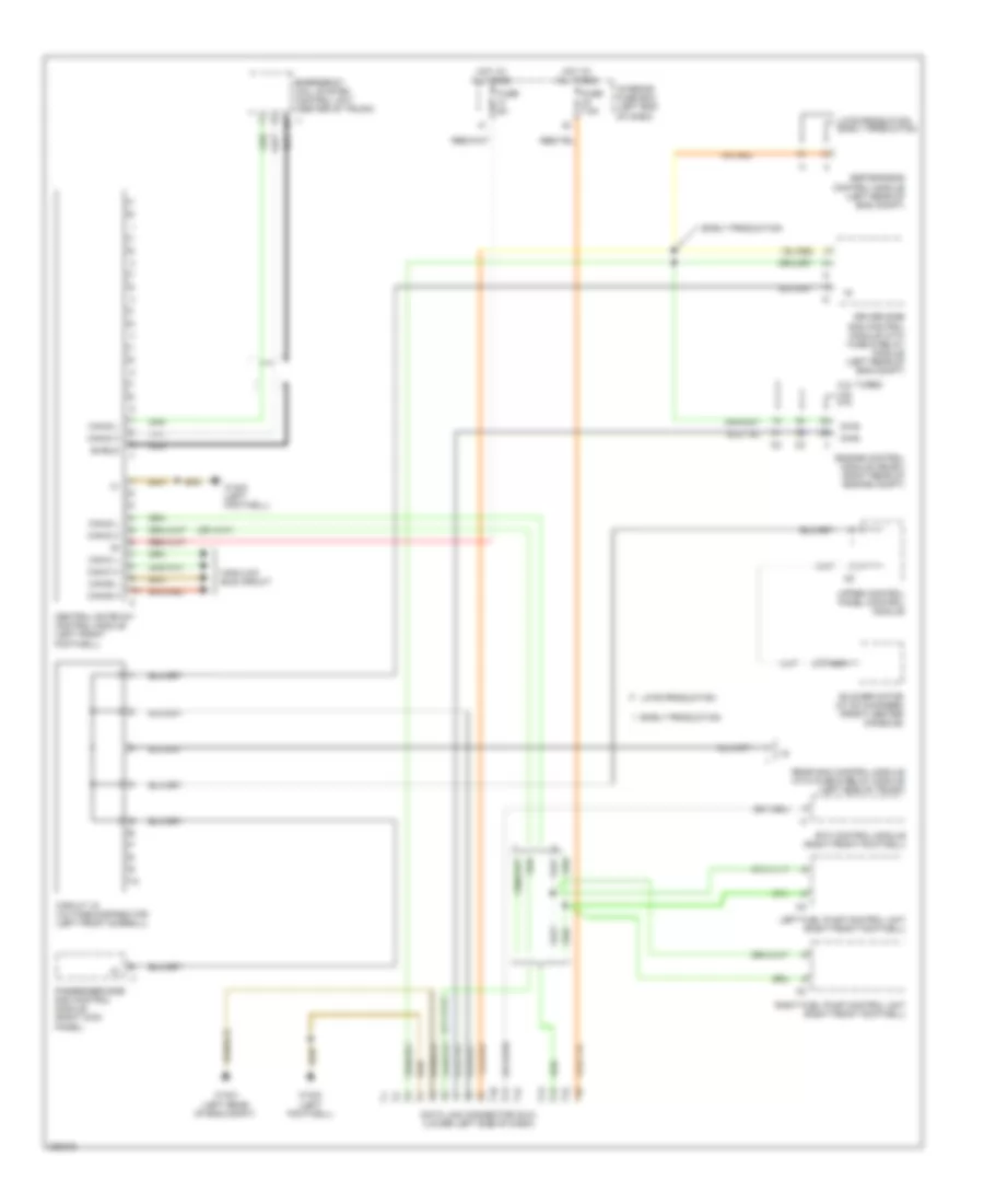
Data Link Connector Wiring Diagram for Mercedes-Benz E350 4Matic 2006
List of elements for Data Link Connector Wiring Diagram for Mercedes-Benz E350 4Matic 2006:
- 3.2l turbo 3.5l 5.0l
- Blower motor (w/ cd changer) (front center console)
- Can-b h
- Can-b l
- Can-c h
- Can-c l
- Can-d h
- Can-d l
- Central gateway control module (left front footwell)
- Circuit 15 voltage distributor (left front doorsill)
- Data link connector (dlc) (lower left side of dash)
- Diag
- Driver side sam control module with fuse & relay module (left rear of eng compt)
- Early production
- Emergency call system control unit (center of trunk)
- Engine control module (me-sfi) (right rear of engine compt)
- Esp/sps/bas control module (left rear of eng compt)
- Etc control module (right front footwell)
- Fuse 5a
- Fuse 7.5a
- High/low bus circuit
- Hot at all times
- Interior fuse box (left end of dash)
- Late production
- Late production early production
- Left fuel pump control unit (right front footwell)
- Nca
- Passenger side sam control module (right kick panel)
- Rear sam control module with fuse & relay module (left side of trunk)
- Right fuel pump control unit (right front footwell)
- Shield
- Upper control panel control module
- W15/2 (left footwell)
- W15/3 (left rear of eng compt)
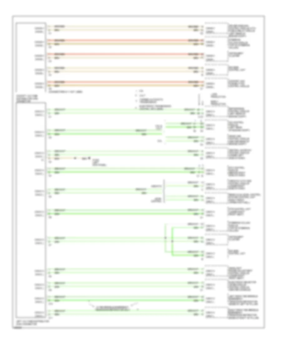
High/Low Bus Wiring Diagram (1 of 2) for Mercedes-Benz E350 4Matic 2006
List of elements for High/Low Bus Wiring Diagram (1 of 2) for Mercedes-Benz E350 4Matic 2006:
- (connectors 6-11 not used)
- 3.2lt
- 3.5l
- 3.5l & 3.2lt
- 5.0l
- 7-speed automatic transmission
- Airmatic
- Airmatic with ads control module (under right side of dash)
- C10
- C11
- Can-b h
- Can-b l
- Can-c h
- Can-c l
- Cdi control module (left rear of engine compt)
- Central gateway control module (under left side of dash)
- Cockpit voltage distributor (can) connector
- Comfort aac pushbutton control module
- Driver side sam control module with fuse & relay module (left rear of engine compt)
- Dtr control unit (under right front seat)
- Early production
- Eis (ezs) control unit
- Electronic selector lever module control module (center console)
- Electronic transmission control (etc (egs))
- Esp/sps/bas control module (left rear of engine compt)
- Etc control module (behind right side of dash)
- Headlight range adjustment control module (under right front seat)
- Instrument cluster
- Late production
- Left front reversible emergency tensioning retractor (base of left "b" pillar)
- Left voltage distributor (can) connector
- Level control
- Me-sfi (me) control module (center rear of engine compt)
- Rear axle level control system control unit (right front upper footwell)
- Right front reversible emergency tensioning retractor (base of right "b" pillar)
- Steering column module (top of steering column)
- W/ reversible emergency tensioning retractor only
- W15/2 (left kick panel)
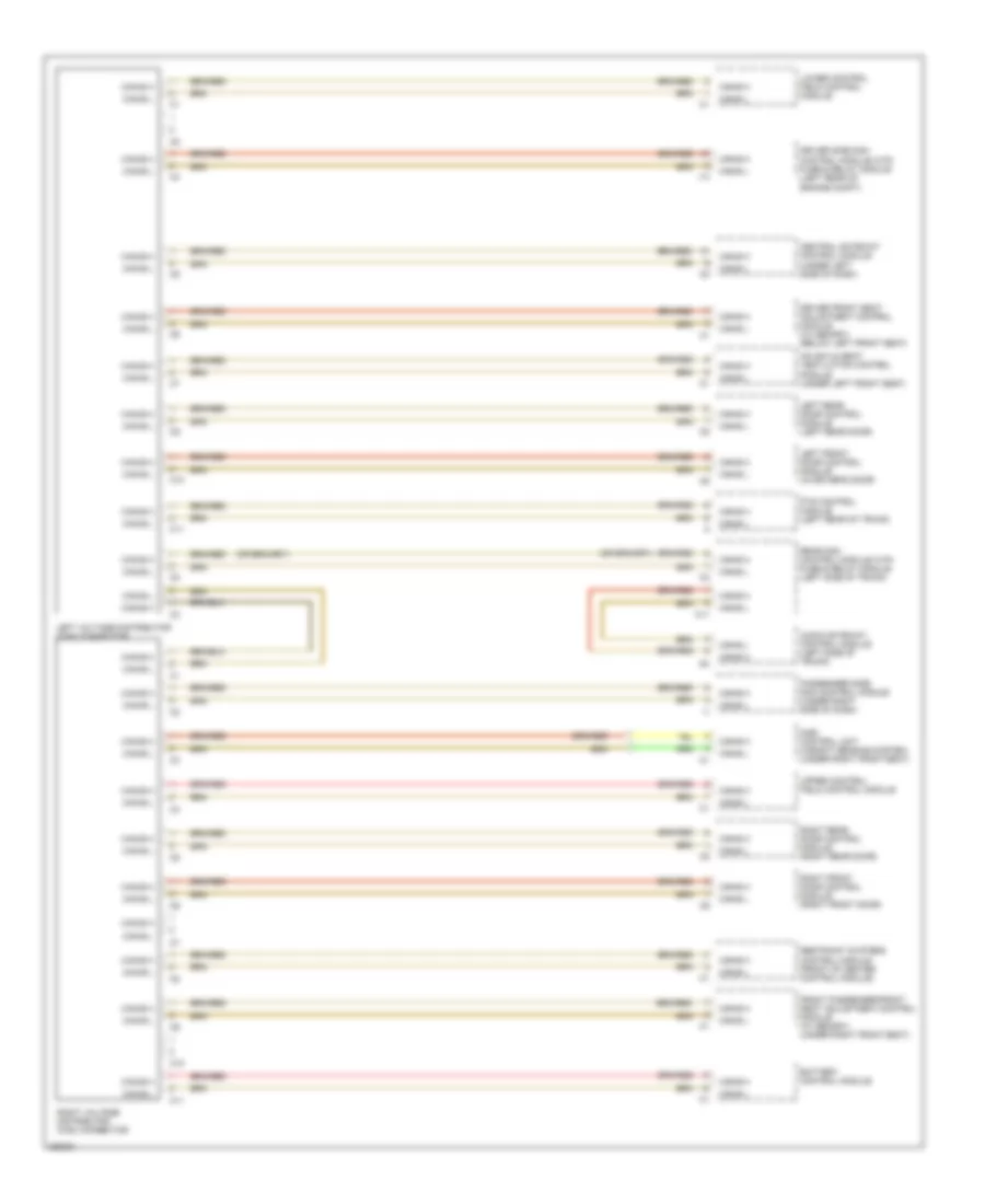
High/Low Bus Wiring Diagram (2 of 2) for Mercedes-Benz E350 4Matic 2006
List of elements for High/Low Bus Wiring Diagram (2 of 2) for Mercedes-Benz E350 4Matic 2006:
- Audio gateway control module (left side of trunk)
- Battery control module
- C10
- C11
- Can-b h
- Can-b l
- Central gateway control module (under left side of dash)
- Driver front seat adjustment control module (w/ memory) (below left front seat)
- Driver side sam control module with fuse & relay module (left rear of engine compt)
- Front passenger front seat adjustment control module (w/ memory) (under right front seat)
- Hs (sih) & seat ventilation control module (under left front seat)
- I13
- Left front door control module (in driver's door)
- Left rear door control module (left rear door)
- Left voltage distributor (can) connector
- Lower control field control module
- Passenger side sam control module (under right side of dash)
- Pts control module (left rear of trunk)
- Rear sam control module with fuse & relay module (left side of trunk)
- Restraint systems control module (front of center control module)
- Right front door control module (right front door)
- Right rear door control module (right rear door)
- Right voltage distributor (can) connector
- Upper control field control module
- Wss control unit (weight sensing system) (under right front seat)

 Čeština
 Dansk
Dansk Deutsch
 Ελληνικά
 English
 Español
 Suomi
Suomi Français
 Français
 עברית
עברית Hrvatski
 Magyar
 Italiano
 日本語
日本語 한국어
한국어 Nederlands
 Polski
 Português
 Português
 Română
 Русский
 Slovenčina
 Slovenščina
 Svenska
 Türkçe
 中文 (中国)