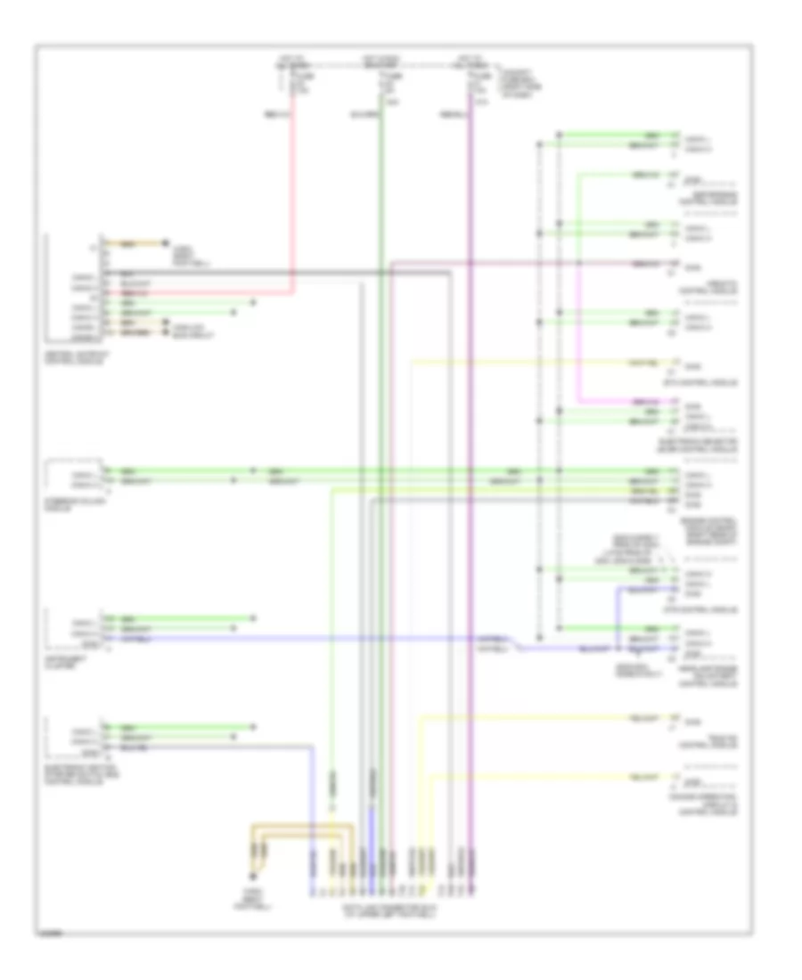
COMPUTER DATA LINES
Data Link Connector Wiring Diagram for Mercedes-Benz S500 2003
List of elements for Data Link Connector Wiring Diagram for Mercedes-Benz S500 2003:
- (2003 & early prod of 2004)
- (2003-2004 models only)
- (late prod of 2004, 2005 & 2006)
- 81a
- 84a
- Airmatic control module
- Can-b h
- Can-b l
- Can-c h
- Can-c l
- Can-d h
- Can-d l
- Central gateway control module
- Cockpit fuse box (right side of dash)
- Comand operating, display & control module
- Data link connector (dlc) (at upper left footwell)
- Diag
- Dtr control module
- Electronic ignition- starter switch (eis) control module
- Electronic selector lever control module
- Engine control module (me-sfi) (right rear of engine compt)
- Esp/sps/bas control module
- Etc control module
- Fuse 10a
- Fuse 5a
- Headlamp range adjustment control module
- High/low bus circuit
- Hot at all times
- Hot in run or start
- Instrument cluster
- Steering column module
- Tele aid control module
- W36/2 (right footwell)
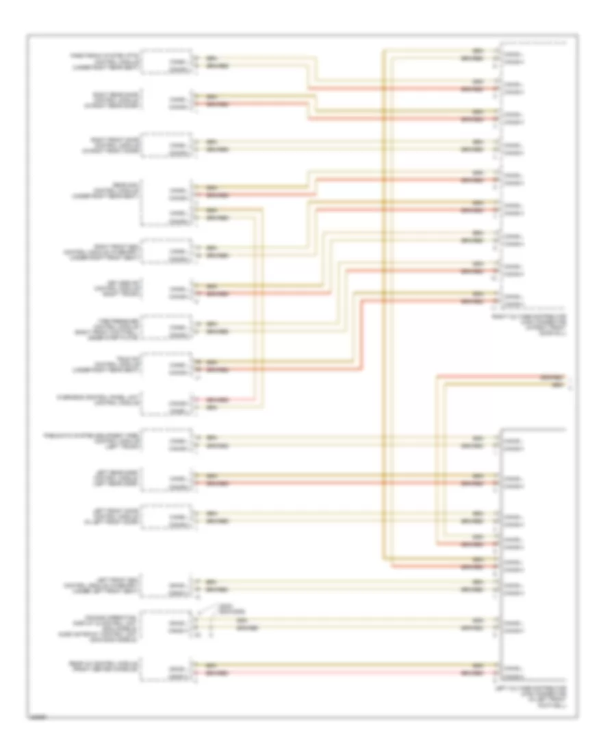
High/Low Bus Wiring Diagram (1 of 2) for Mercedes-Benz S500 2003
List of elements for High/Low Bus Wiring Diagram (1 of 2) for Mercedes-Benz S500 2003:
- (2003) (2004-2006)
- Can-b h
- Can-b l
- Comand operating, display & control unit (2003 models) audio gateway control unit (2004-2006 models)
- Keyless go control module (right trunk)
- Left front door control module (in left front door)
- Left front esa control module (w/memory) (under left front seat)
- Left rear door control module (left rear door)
- Left voltage distributor (can) connector (in left front footwell)
- Overhead control panel unit control module
- Parktronic system (pts) control module (under right rear seat)
- Pneumatic system equipment (pse) control module (left trunk)
- Rear a/c control module (front center console)
- Rear sam control module (under right rear seat)
- Right front door control module (in right front door)
- Right front esa control module (w/memory) (under right front seat)
- Right rear door control module (in right rear door)
- Right voltage distributor (can) connector (in right front door sill)
- Tele aid control module (under right rear seat)
- Tire pressure control module (right front footwell, under step plate)
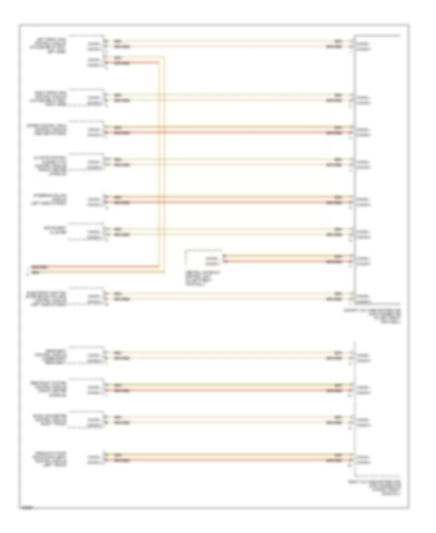
High/Low Bus Wiring Diagram (2 of 2) for Mercedes-Benz S500 2003
List of elements for High/Low Bus Wiring Diagram (2 of 2) for Mercedes-Benz S500 2003:
- Can-b h
- Can-b l
- Central gateway control unit (in left front footwell)
- Climate control pushbutton control module (front center console)
- Cockpit voltage distributor (can) connector (in left front footwell)
- Dc/dc converter control module (right trunk)
- Electronic ignition- starter switch (eis) control module (left side of dash)
- Instrument cluster
- Left front sam control module (in fuse relay box, left side)
- Pneumatic pump for dynamic seat control module (left trunk)
- Rear seat control module (under right rear seat)
- Restraint system control module (front center console)
- Right front sam control module (in fuse relay box, right side)
- Right voltage distributor (can) connector (in right front door sill)
- Steering column module (left side of dash)
- Upper control field control module (center of dash)

 Čeština
 Dansk
Dansk Deutsch
 Ελληνικά
 English
 Español
 Suomi
Suomi Français
 Français
 עברית
עברית Hrvatski
 Magyar
 Italiano
 日本語
日本語 한국어
한국어 Nederlands
 Polski
 Português
 Português
 Română
 Русский
 Slovenčina
 Slovenščina
 Svenska
 Türkçe
 中文 (中国)