Čeština
 Dansk
Dansk Deutsch
 Ελληνικά
 English
 Español
 Suomi
Suomi Français
 Français
 עברית
עברית Hrvatski
 Magyar
 Italiano
 日本語
日本語 한국어
한국어 Nederlands
 Polski
 Português
 Português
 Română
 Русский
 Slovenčina
 Slovenščina
 Svenska
 Türkçe
 中文 (中国)

MEMORY SYSTEMS
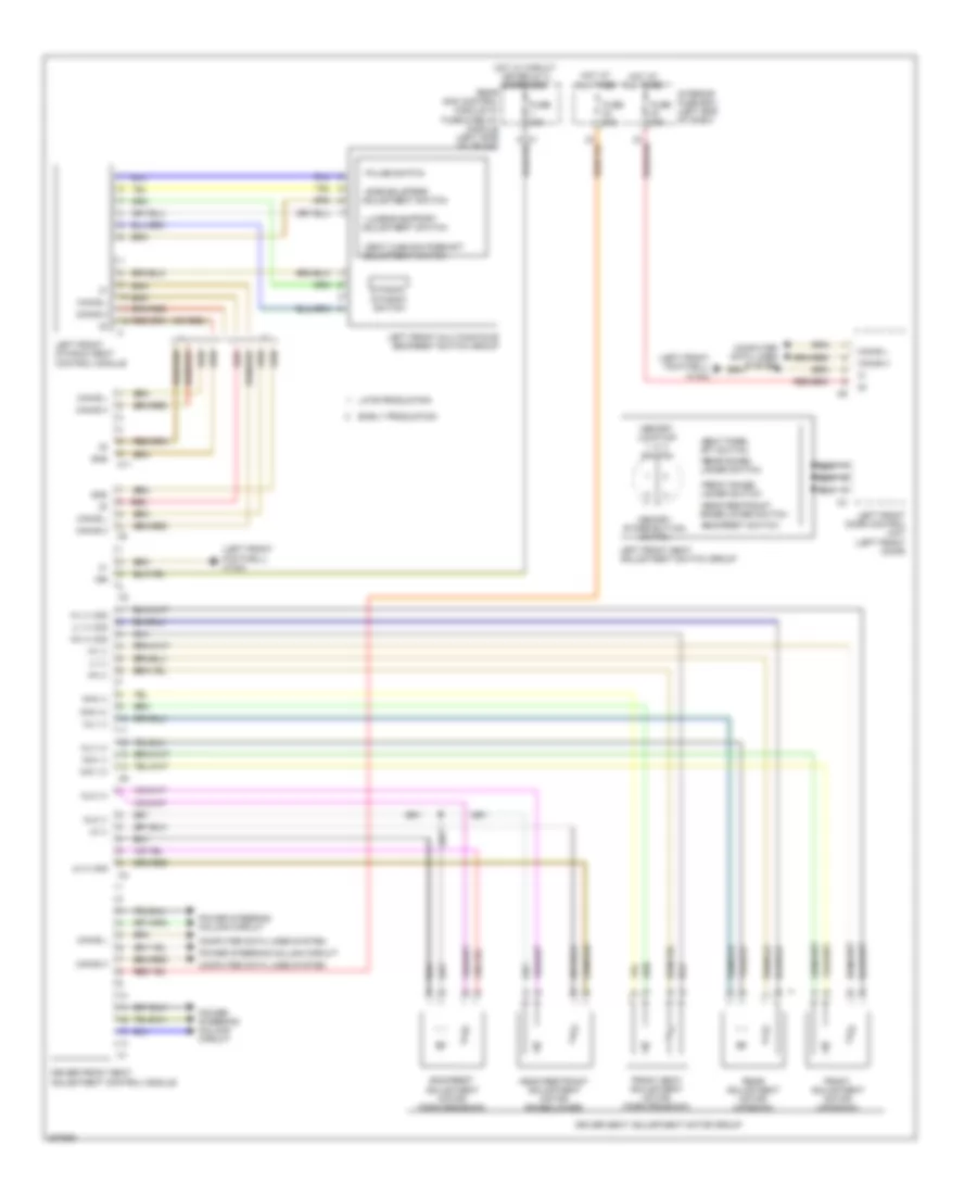
Driver"s Memory Seat Wiring Diagram for Mercedes-Benz CLS500 2006
List of elements for Driver"s Memory Seat Wiring Diagram for Mercedes-Benz CLS500 2006:

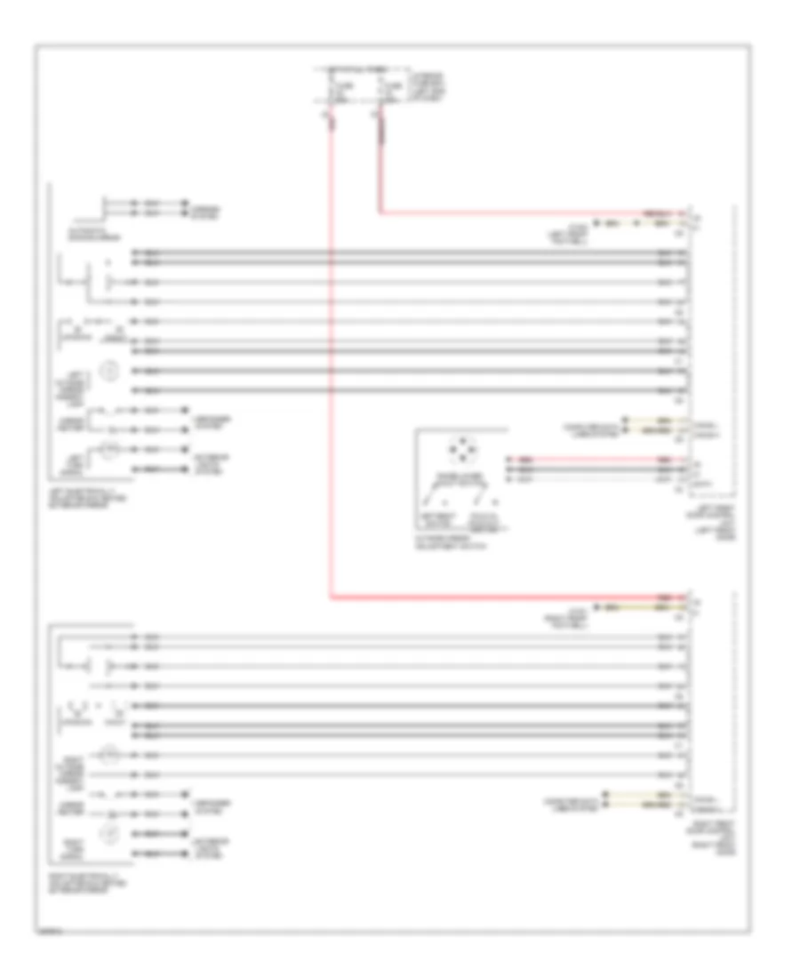
Memory Mirrors Wiring Diagram for Mercedes-Benz CLS500 2006
List of elements for Memory Mirrors Wiring Diagram for Mercedes-Benz CLS500 2006:
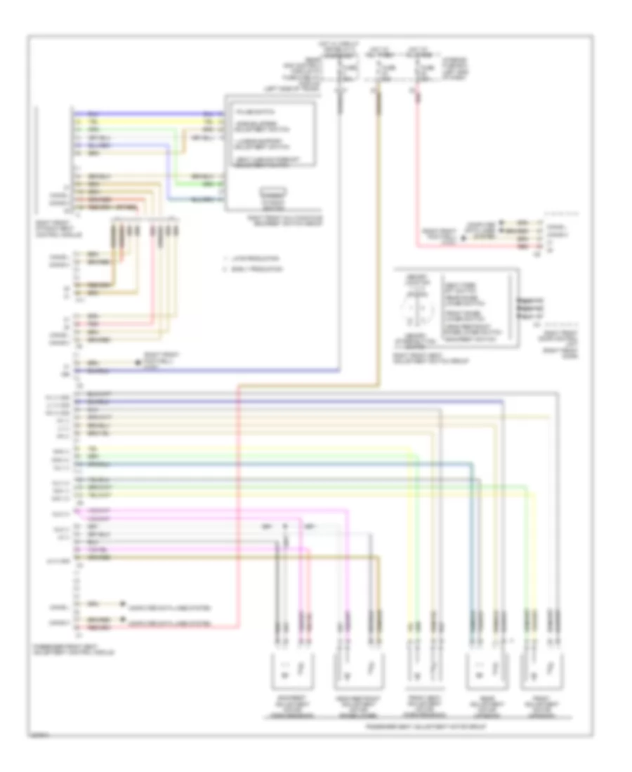
Passenger"s Memory Seat Wiring Diagram for Mercedes-Benz CLS500 2006
List of elements for Passenger"s Memory Seat Wiring Diagram for Mercedes-Benz CLS500 2006:
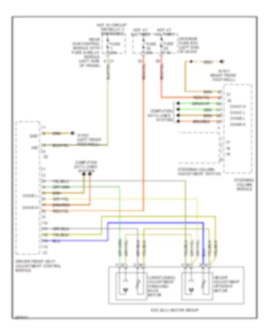
Steering Column Memory Wiring Diagram for Mercedes-Benz CLS500 2006
List of elements for Steering Column Memory Wiring Diagram for Mercedes-Benz CLS500 2006: