ANTI-LOCK BRAKES
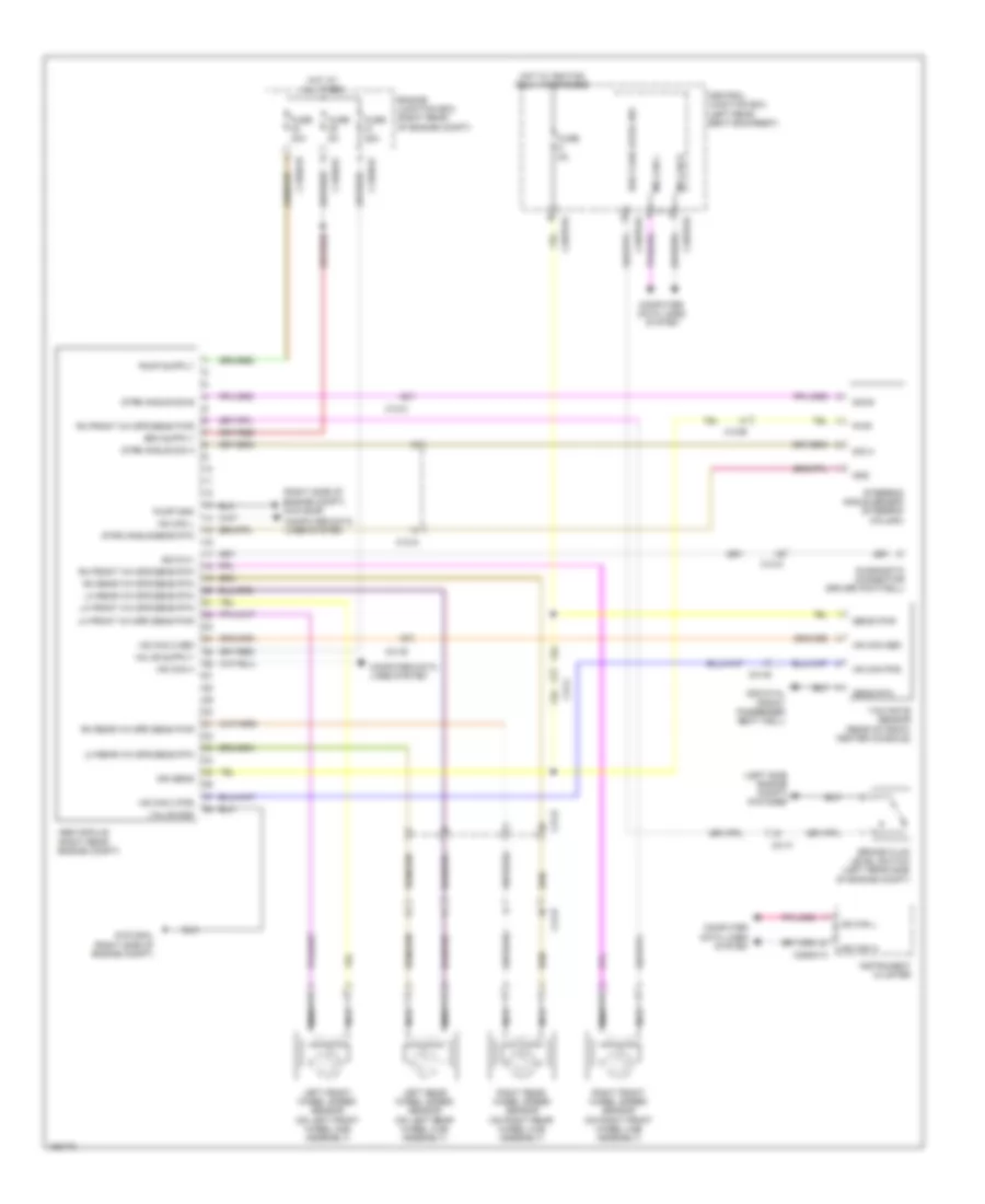
Anti-lock Brakes Wiring Diagram for Jaguar XJR 2014
List of elements for Anti-lock Brakes Wiring Diagram for Jaguar XJR 2014:
- (left side engine compt) g1d122bs
- (right side of engine compt) g1d125ar
- Abs module (right rear engine compt)
- Brake fluid level switch (left rear side of engine compt)
- Brk fluid level sw
- C12-a
- C12-b
- C1bb01c
- C1bb01d
- C2mc01a
- C31-b
- C31-c
- C31-f
- C3bp01b
- C3bp01d
- C3bp01e
- C44-b
- Central junction box (left rear seat backrest)
- Computer data lines system
- Diagnostic connector (driver footwell)
- Engine junction box (right rear of engine compt)
- Fuse 25a
- Fuse 40a
- Fuse 5a
- G1d125al (right side of engine compt)
- G3d181al (front passenger seat well)
- Gnd
- Hot at all times
- Hot w/ ignition relay energized
- Hs can 2 pos
- Hs can h
- Hs can l
- Hs can pos
- Ign sens
- Instrument cluster
- Iso 9141
- Left front wheel speed sensor (on left front wheel hub assembly)
- Left rear wheel speed sensor (on left rear wheel hub assembly)
- Lh front wh spd sens pwr
- Lh front wh spd sens rtn
- Lh rear wh spd sens rtn
- Ms can h
- Ms can l
- Nca
- Pump gnd
- Pwr
- Rh front wh spd sens pwr
- Rh front wh spd sens rtn
- Rh rear wh spd sens pwr
- Rh rear wh spd sens rtn
- Right front wheel speed sensor (on right front wheel hub assembly)
- Right rear wheel speed sensor (on right rear wheel hub assembly)
- Sens pwr
- Sens rtn
- Sig a
- Sig b
- Steering angle sensor (steering column)
- Strg angle sens rtn
- Strg angle sig a
- Strg angle sig b
- Valve gnd
- Yaw rate sensor (rear of front center console)
 English