AIR CONDITIONING
Heater Wiring Diagram for Hyundai Accent GL 1999

List of elements for Heater Wiring Diagram for Hyundai Accent GL 1999:
- (right kick panel) g203
- Blower fuse 30a
- Blower motor (behind right side of dash)
- Blower relay (in passenger compartment relay box)
- Blower resistors (behind right side of dash, in blower motor housing)
- Blower switch
- Dash fuse box (below left side of dash, at kick panel)
- Engine compartment relay & fuse box (on left side of engine compartment, in front of shock tower)
- Fresh
- Fresh/recirc switch & heater control panel illumination
- Fuse 10 10a
- Fuse 16 10a
- Headlights system
- Hot at all times
- Hot in on
- Hot in on or start
- Ind
- J/c (i15) (behind center of dash)
- Nca
- Off
- Power windows system
- Rec
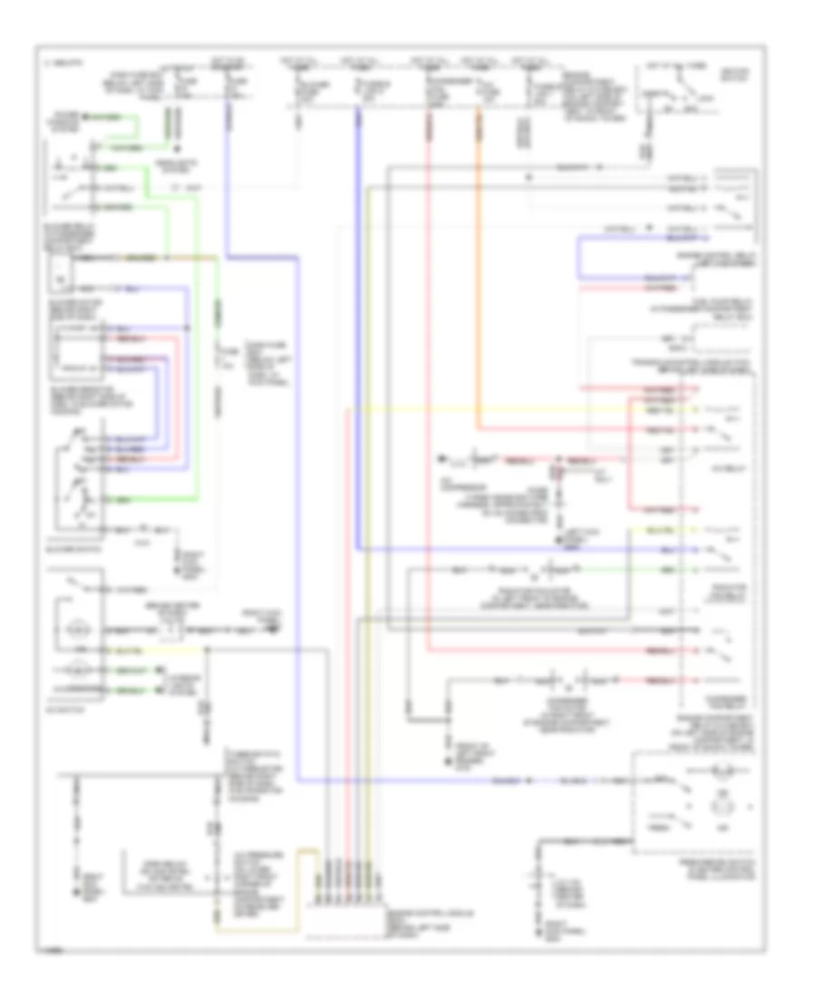
Manual A/C Wiring Diagram for Hyundai Accent GL 1999
List of elements for Manual A/C Wiring Diagram for Hyundai Accent GL 1999:
- (behind center of dash) j/c (i15)
- (front of left front fender) g100
- (right kick panel) g203
- 1995 vftc c
- A/c compressor
- A/c fuse 10a
- A/c pressure switch (on lower right front corner of engine compartment, on receiver- dryer)
- A/c relay
- A/c switch
- A/t only
- Acc
- Blower fuse 30a
- Blower motor (behind right side of dash)
- Blower relay (in passenger compartment relay box)
- Blower resistor (behind right side of dash, in blower motor housing)
- Blower switch
- Condenser fan fuse 20a
- Condenser fan motor (in right front of engine compartment, near radiator)
- Condenser fan relay
- Dash fuse box (below left side of dash, at kick panel)
- Diode (taped inside ecm wire harness, approximately six (6) inches from connector)
- E38-2
- Engine compartment relay & fuse box (on left side of engine compart- ment, in front of shock tower)
- Engine compartment relay & fuse box (on left side of engine compartment, in front of shock tower)
- Engine control module (ecm) (behind left side of dash)
- Engine control relay (left kick panel)
- Fresh
- Fresh/recirc switch & heater control panel illumination
- Fuel pump relay (in passenger compartment relay box)
- Fuse 10a
- Fusible link 1 20a
- Fusible link d 20a
- Headlights system
- Hot at all times
- Hot in on
- Hot in on or start
- Ignition switch
- Illumination
- Ind
- Interior lights system
- J/c (i15) (behind center of dash)
- Lock
- M101
- Nca
- Off
- Open below 200 kpa (29 psi) or above 3140 kpa (455 psi)
- Power windows system
- Radiator fan motor (in left front of engine compartment, near radiator)
- Radiator fan relay
- Rec
- Start
- Thermostatic switch (w/thermistor) (behind right side of dash, in evaporator housing)
- Transaxle control module (tcm) (behind left side of dash)