ANTI-LOCK BRAKES
Anti-lock Brake Wiring Diagrams for Hyundai Accent GS 2001
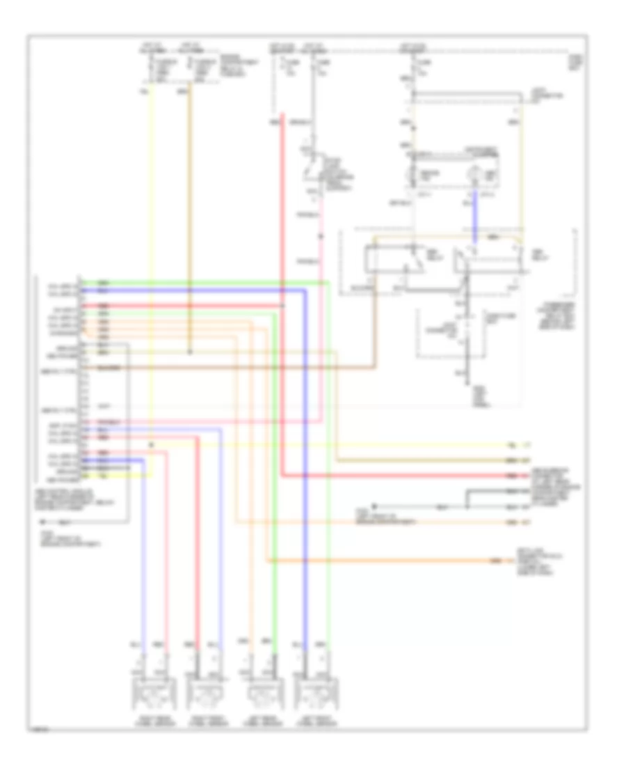
List of elements for Anti-lock Brake Wiring Diagrams for Hyundai Accent GS 2001:
- (at left rear corner of engine compartment, near master cylinder)
- Abs bleeding connector
- Abs control module (left rear corner of engine compartment, below master cylinder)
- Abs ind
- Abs relay
- Abs rly ctrl
- Brake ind
- Dash fuse box
- Data link connector (dlc) (partial) (lower left side of dash)
- Diagnosis
- Ebd relay
- Ebd rly ctrl
- Engine compartment relay & fuse box
- Fuse 10a
- Fusible link 1 (abs) 30a
- Fusible link 2 (abs) 30a
- G100 (left front of engine compartment)
- G200 (left kick panel)
- Ground
- Hot at all times
- Hot in on or start
- Instrument cluster
- Joint connector m31
- Left front wheel sensor
- Left rear wheel sensor
- M71-1
- M71-3
- Mem power
- Nca
- On input
- Passenger compartment relay box (behind left side of dash)
- Red
- Right front wheel sensor
- Right rear wheel sensor
- Sop lp sw
- Stop- lamp switch (on brake pedal support)
- Whl spd in
 English