ANTI-LOCK BRAKES
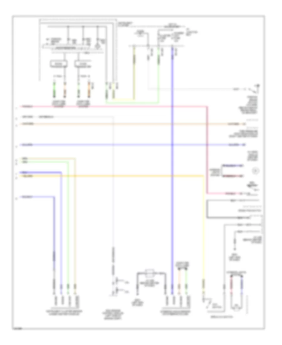
Anti-lock Brakes Wiring Diagram (1 of 2) for Hyundai Genesis 4.6 2010

List of elements for Anti-lock Brakes Wiring Diagram (1 of 2) for Hyundai Genesis 4.6 2010:
- Abs pump motor
- Auto vehicle hold sw
- Brake switch signal
- Can high
- Can low
- Computer data lines system
- E/r-e1a
- E/r-e2b
- Ecs switch
- Engine room junction box (right rear of engine compt)
- Esc control module (left front of engine compt)
- Esp fuse 10a
- Esp-1 fuse 30a
- Esp-2 fuse 30a
- Fuse & relay box (engine room) (left side of engine compt)
- Ge02 (right kick panel)
- Geo2 (right kick panel)
- Ground
- High
- Hot at all times
- Hot in on or start
- J/c jeb (left kick panel)
- K-line
- Left front wheel sensor (on left front wheel hub assembly)
- Left rear wheel sensor (left rear wheel hub assembly)
- Low
- M51-b
- Nca
- Note: esc control module contains: esc solenoids, esc pump motor
- On/start input
- Pdm (left center of dash)
- Pnk
- Power
- Red
- Right front wheel sensor (on right front wheel hub assembly)
- Right rear wheel sensor (right rear wheel hub assembly)
- Stop lamp relay
- Stop lamp relay control
- Stop lamp switch
- Stop lamp switch (above brake pedal, on bracket)
- Stop lp fuse 10a
- W/ button start
- W/ epb
- Wheel sensor fl_gnd
- Wheel sensor fl_sig
- Wheel sensor fr_gnd
- Wheel sensor fr_sig
- Wheel sensor rl_gnd
- Wheel sensor rl_sig
- Wheel sensor rr_gnd
- Wheel sensor rr_sig
- Wheel spd sig
- Wheel spd sig av head module
- Wheel spd sig ecm
- Wheel spd sig pdm
Anti-lock Brakes Wiring Diagram (2 of 2) for Hyundai Genesis 4.6 2010
List of elements for Anti-lock Brakes Wiring Diagram (2 of 2) for Hyundai Genesis 4.6 2010:
- 3.8l
- 4.6l
- Abs ind
- Av head module (center of dash)
- Avh
- B-can transceiver
- C-can transceiver
- Can high
- Can low
- Chassis unit fuse 10a
- Cluster fuse 10a
- Computer data lines system
- Crash pad switch
- Ctg-k
- Diode
- Ecm (engine control module) (left side of engine compt)
- Elg-a
- Epb & avh switch
- Esc ind
- Esc off ind
- Esc switch
- Gm01 (left end of dash)
- Ground
- Hot in on or start
- I/p junction box
- I/p-lhc
- I/p-lhe
- I/p-lhf
- Ill.
- Instrument cluster
- Instrument cluster sensor (under center console)
- Interior lights system
- J/c jme (behind center of dash)
- M11-a
- M11-b
- Mcu
- Parking brake ind
- Parking brake switch (w/o epb) (above parking brake pedal, on bracket)
- Power
- Shift resistor
- Steering angle sensor (on steering column)
- Switch
- Tire pressure monitoring module (right center of dash)