ANTI-LOCK BRAKES
Anti-lock Brake Wiring Diagrams for Hyundai Sonata GLS 1998
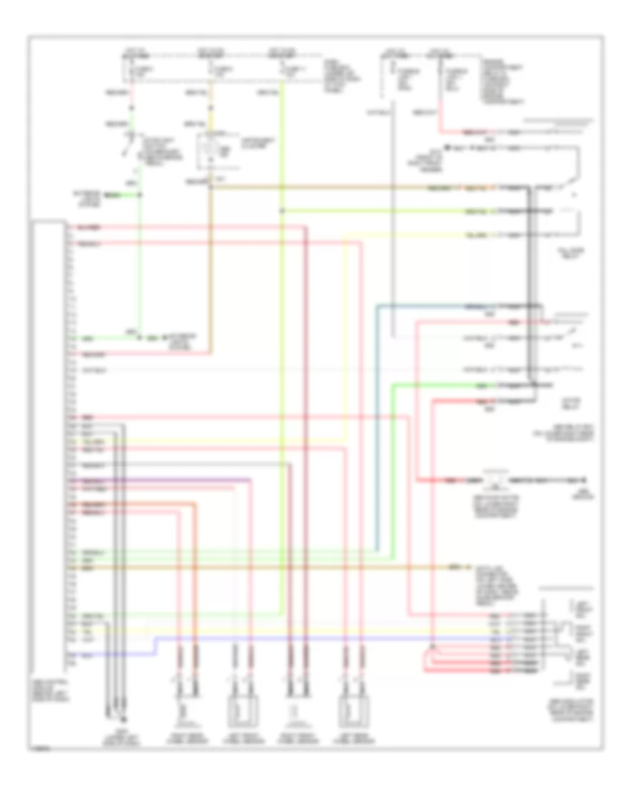
List of elements for Anti-lock Brake Wiring Diagrams for Hyundai Sonata GLS 1998:
- Abs control module (behind left side of dash)
- Abs ground
- Abs ind
- Abs modulator (on lower right rear of engine compartment)
- Abs pump motor (on lower right rear of engine compartment)
- Abs relay box (on lower right rear of engine compt)
- Dash fuse box (under let side of dash, at kick panel)
- Data link connector (on left side lower center of dash, above accelerator pedal)
- E05
- E06
- Engine compartment relay & fuse box (on right side of engine compartment)
- Exterior lights system
- Fail safe relay
- Fuse 11 10a
- Fuse 2 15a
- Fuse 8 10a
- Fusible link i 30a (pnk)
- G101 (front of right front fender)
- G202 (upper left side of dash)
- Hot at all times
- Hot in on or start
- I16-3
- Instrument cluster
- Left front sol
- Left front wheel sensor
- Left rear sol
- Left rear wheel sensor
- Motor relay
- Nca
- Red
- Right front sol
- Right front wheel sensor
- Right rear sol
- Right rear wheel sensor
- Stoplight switch (on bracket, above brake pedal)
 English