ANTI-LOCK BRAKES
Anti-lock Brake Wiring Diagrams for Infiniti G20 1993
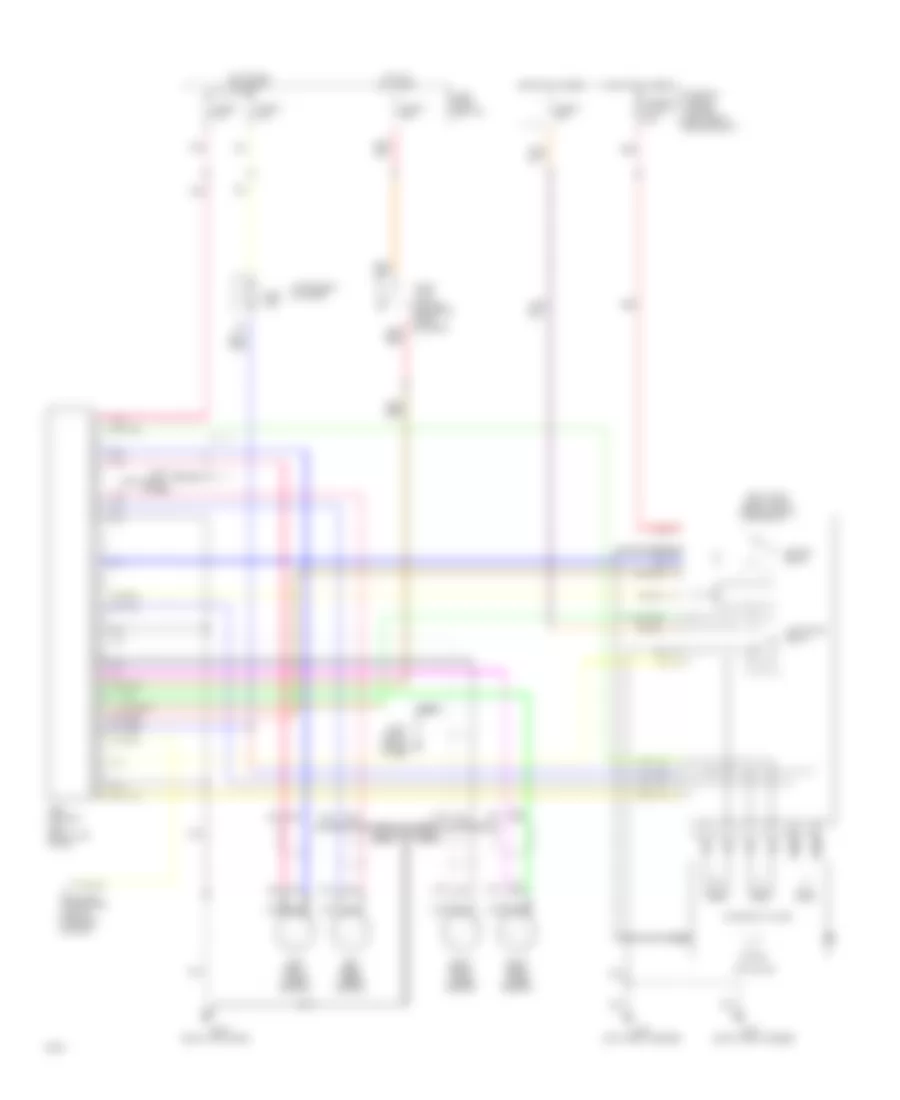
List of elements for Anti-lock Brake Wiring Diagrams for Infiniti G20 1993:
- (left front fender)
- (left shock
- (right front engine compt)
- (right front fender)
- (right kick panel)
- (right shock tower)
- Abs control
- Abs ind.
- Actuator
- Actuator relay
- All times
- Data link connector (left of steering column)
- Fuse 4 20a
- Fuse and fusible link box (left front engine compt)
- Fuse block (left i/p)
- Fuse u 10a
- Fuse x 20a
- Fuse z 10a
- Fusible link g 30a
- G100
- G101
- G102
- G103
- G203
- Hot at
- Hot at all times
- Hot in run or start
- Instrument cluster
- Left front wheel sensor
- Left rear wheel sensor
- Motor
- Motor relay
- Nca
- Pnk
- Red
- Relay box
- Right front wheel sensor
- Right rear wheel sensor
- Solenoid valves
- Stop lamp switch (on brake pedal support)
- Tower)
- Unit (right kick panel)
 English