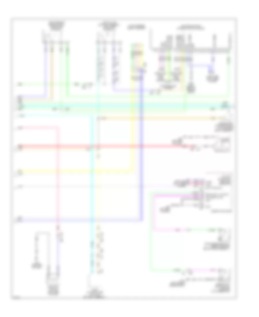
ANTI-LOCK BRAKES
Anti-lock Brakes Wiring Diagram, Except Hybrid (1 of 2) for Infiniti Q50 Premium 2014

List of elements for Anti-lock Brakes Wiring Diagram, Except Hybrid (1 of 2) for Infiniti Q50 Premium 2014:
- (left end of dash) chassis control module
- (left end of dash) m93
- (left rear of engine compt) e140
- (or red)
- Abs actuator & electric unit (control unit) (left rear of engine compt)
- B6 c1
- Can-h
- Can-l
- Chas comm h
- Chas comm l
- Computer data lines
- Computer data lines system
- E121
- E137 (left rear of engine compt)
- E25
- E3 b10
- E47
- Fr-lh sen pwr
- Fr-lh sen sig
- Fr-rh sen pwr
- Fr-rh sen sig
- Fuse & fusible link block (on battery positive (+) post)
- Fuse 54 10a
- Fusible link l 30a
- Fusible link n 50a
- Gnd
- Hot at all times
- Hot w/ ignition relay energized
- Ign
- Ipdm e/r (intelligent power distribution module engine room) (right rear of engine compt)
- Left rear wheel sensor (on left rear wheel hub assembly)
- M39
- M40
- M93 (left end of dash)
- Mtr batt
- Pnk
- Red
- Right rear wheel sensor (on right rear wheel hub assembly)
- Rr-lh sen pwr
- Rr-lh sen sig
- Rr-rh sen pwr
- Rr-rh sen sig
- Sel sw (dn)
- Sel sw (up)
- Shield
- Steering angle sensor (upper steering column)
- Stp lp sw sig
- System
- Tan
- Transmissions system
- Triple switch
- Vac sen gnd
- Vac sen pwr
- Vac sen sig
- Vacuum sensor (on brake vacuum booster)
- Vdc off sw sig
- Vdc off switch
- Vlv batt
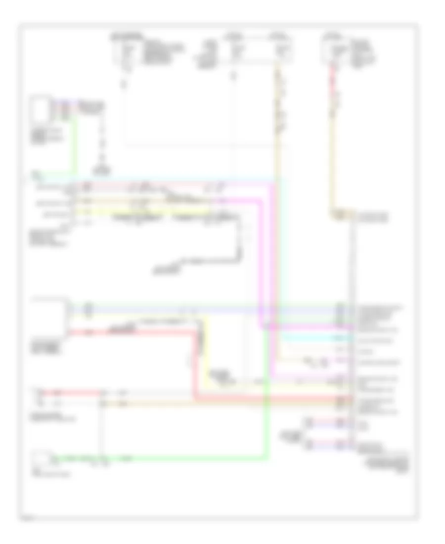
Anti-lock Brakes Wiring Diagram, Except Hybrid (2 of 2) for Infiniti Q50 Premium 2014
List of elements for Anti-lock Brakes Wiring Diagram, Except Hybrid (2 of 2) for Infiniti Q50 Premium 2014:
- 11f
- 28c
- 32c
- B39
- Batt pwr sply
- Brake fluid level switch (in brake fluid reservoir)
- Brk fluid lvl sw sig
- Can-h
- Can-l
- Combination meter
- Computer data lines system
- E137 (left rear of engine compt)
- E25
- E25 m40
- E64
- E65
- Exterior lights system
- Fuse 11 5a
- Fuse 12 10a
- Fuse 19 10a
- Fuse 6 10a
- Fuse block (j/b) (left kick panel)
- Gnd
- Hot at all times
- Hot w/ ignition relay energized
- Icc brake hold relay (w/ icc) (right rear of engine compt)
- Ign sig
- Left front wheel sensor (on left front wheel hub assembly)
- M133
- M40
- M57
- M58
- M93 (left end of dash)
- Parking brake switch (base of parking brake lever assembly)
- Pnk
- Prk brk sw sig
- Red
- Resistor (w/ icc) (right end of dash)
- Right front wheel sensor (on right front wheel hub assembly)
- Shift interlock system
- Stop lamp switch (top of brake pedal assembly)
- Tan
- Vdc ind, vdc off ind, abs ind & brake ind
- W/ icc
- W/o icc
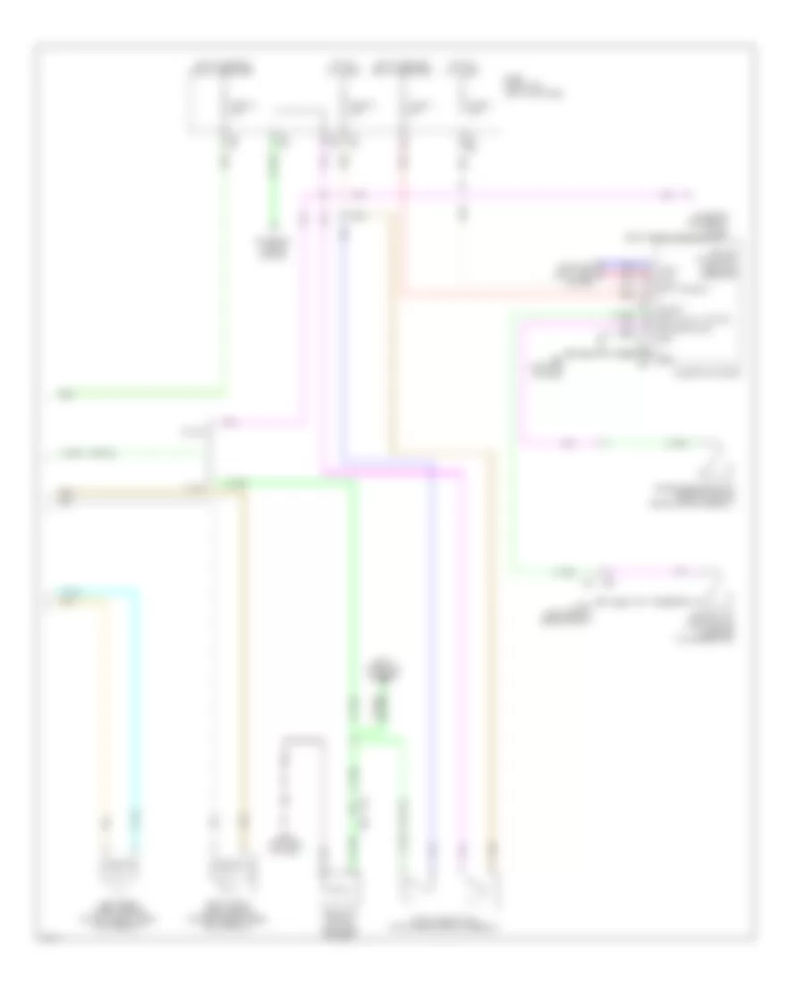
Anti-lock Brakes Wiring Diagram, Hybrid (1 of 3) for Infiniti Q50 Premium 2014
List of elements for Anti-lock Brakes Wiring Diagram, Hybrid (1 of 3) for Infiniti Q50 Premium 2014:
- (right rear of engine compt) icc brake hold relay
- (top of li-ion battery assembly) adas control unit
- 10f
- 11f
- 26c
- 28c
- Abs actuator & electric unit (left rear of engine compt)
- B10
- B29
- B39
- B5 c2
- Brake comm-h
- Brake comm-l
- Brake posi switch sig
- Can-h
- Can-l
- Comm-h
- Comm-l
- Computer data lines system
- E140 (left rear of engine compt)
- E3 b10
- E64
- E65
- Exterior lights system
- Fr lh wheel sens pwr sply
- Fr lh wheel sens sig
- Fr rh wheel sens pwr sply
- Fr rh wheel sens sig
- Fuse & fusible link block (left front of engine compt)
- Fuse 10a
- Fuse block (j/b) (left kick panel)
- Fusible link l 30a
- Fusible link n 50a
- G sens pwr sply
- G sensor gnd
- G sensor sig (+)
- G sensor signal (-)
- Gnd
- Hold rly sig
- Hot at all times
- Hot w/ ignition relay energized
- Ign
- Left front wheel sensor (on left front wheel hub assembly)
- Left rear wheel sensor (on left rear wheel hub assembly)
- M133
- Master cylinder pressure sensor (on brake master cylinder)
- Motor battery
- Pnk
- Press sens gnd
- Press sens pwr sply
- Press sens sig
- Red
- Right front wheel sensor (on right front wheel hub assembly)
- Right rear wheel sensor (on right rear wheel hub assembly)
- Rr lh wheel sens pow sply
- Rr lh wheel sens sig
- Rr rh wheel sens pow sply
- Rr rh wheel sens sig
- Shift interlock system
- Stop lamp sw sig
- Stop lamp switch (top of brake pedal assembly)
- Tan
- Valve battery
- Vdc off sw sig
- W/ icc
- W/o icc
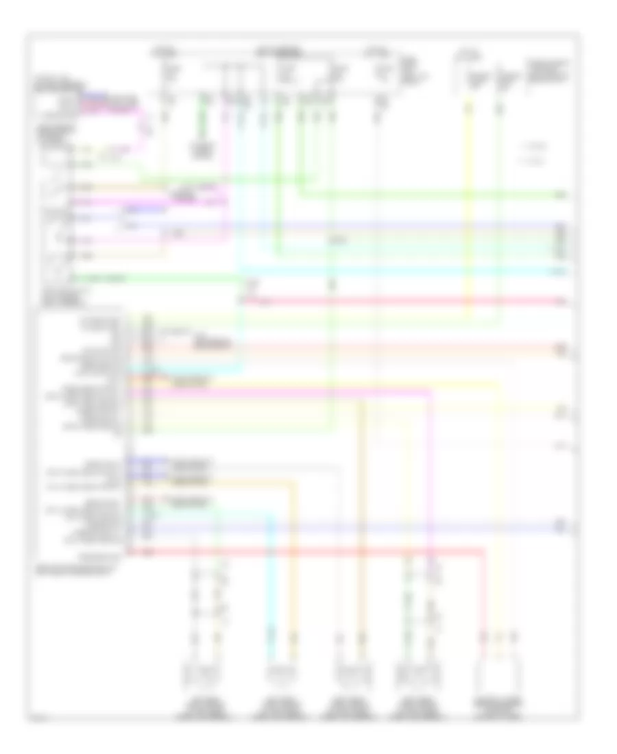
Anti-lock Brakes Wiring Diagram, Hybrid (2 of 3) for Infiniti Q50 Premium 2014
List of elements for Anti-lock Brakes Wiring Diagram, Hybrid (2 of 3) for Infiniti Q50 Premium 2014:
- (left end of dash) chassis control module
- (right rear of engine compt) stop lamp off relay 1
- (top of li-ion battery assembly) stop lamp off relay 2
- B10
- B15
- B17
- B18
- B29
- B30
- Batt pwr sply
- Brake fluid level switch (in brake fluid reservoir)
- Brake pedal position switch (top of brake pedal assembly)
- Brk fluid lvl sw sig
- Can-h
- Can-l
- Chas comm h
- Chas comm l
- Combination meter
- Computer data lines system
- E137 (left rear of engine compt)
- E25
- E25 m40
- E47
- Gnd
- Hpcm (top right side of li-ion battery assembly)
- Ign
- M18
- M19
- M39
- M40
- M57
- M58
- M93 (left end of dash)
- Parking brake switch (base of parking brake lever assembly)
- Pnk
- Prk brk sw sig
- Red
- Resistor (w/ icc) (right end of dash)
- Sel sw (dn)
- Sel sw (up)
- Stp lmp rly 1
- Stp lmp rly 2
- Tan
- Transmissions system
- Triple switch
- Vdc ind, vdc off ind, abs ind & brake ind
- Vdc off switch
- Yaw rate/side/ decel g sensor
Anti-lock Brakes Wiring Diagram, Hybrid (3 of 3) for Infiniti Q50 Premium 2014
List of elements for Anti-lock Brakes Wiring Diagram, Hybrid (3 of 3) for Infiniti Q50 Premium 2014:
- (left rear of engine compt) e137
- B10
- B18
- B29
- B30
- B33
- B35
- Batt
- Battery terminal w/ fusible link (on battery positive (+) post)
- Bcm (right end of dash)
- Brake c0mm-h
- Brake c0mm-l
- Brake pwr sply sig
- Brk pwr sply
- Brk pwr sply sig
- Buzzer pwr sply
- Buzzer sig
- Can-h
- Can-l
- Computer data lines system
- Control module batt
- Dr sw sig
- E121
- E137 (left rear of engine compt)
- E138 (left rear of engine compt)
- E25
- E50
- E53
- Electrically-driven intelligent brake unit (left rear of engine compt)
- Fuse & fusible link block 1 (top of li-ion battery assembly)
- Fuse 10a
- Fusible link d 50a
- Gnd
- H12
- Hot at all times
- Hot w/ ignition relay energized
- Ipdm e/r (intelligent power distribution module engine room) (right rear of engine compt)
- M15
- M19
- M40
- M93 (left end of dash)
- Motor battery
- Pnk
- Pwr sw
- Red
- Shield
- Steering angle sensor (upper steering column)
- Stop lamp sw sig
- Stroke sens 1 sig
- Stroke sens 2 sig
- Stroke sens gnd
- Stroke sens pwr sply
- Stroke sensor (top of brake pedal assembly)
- T22 (top of li-ion battery assembly)
- T27
- Warning buzzer (under right headlamp)