ANTI-THEFT
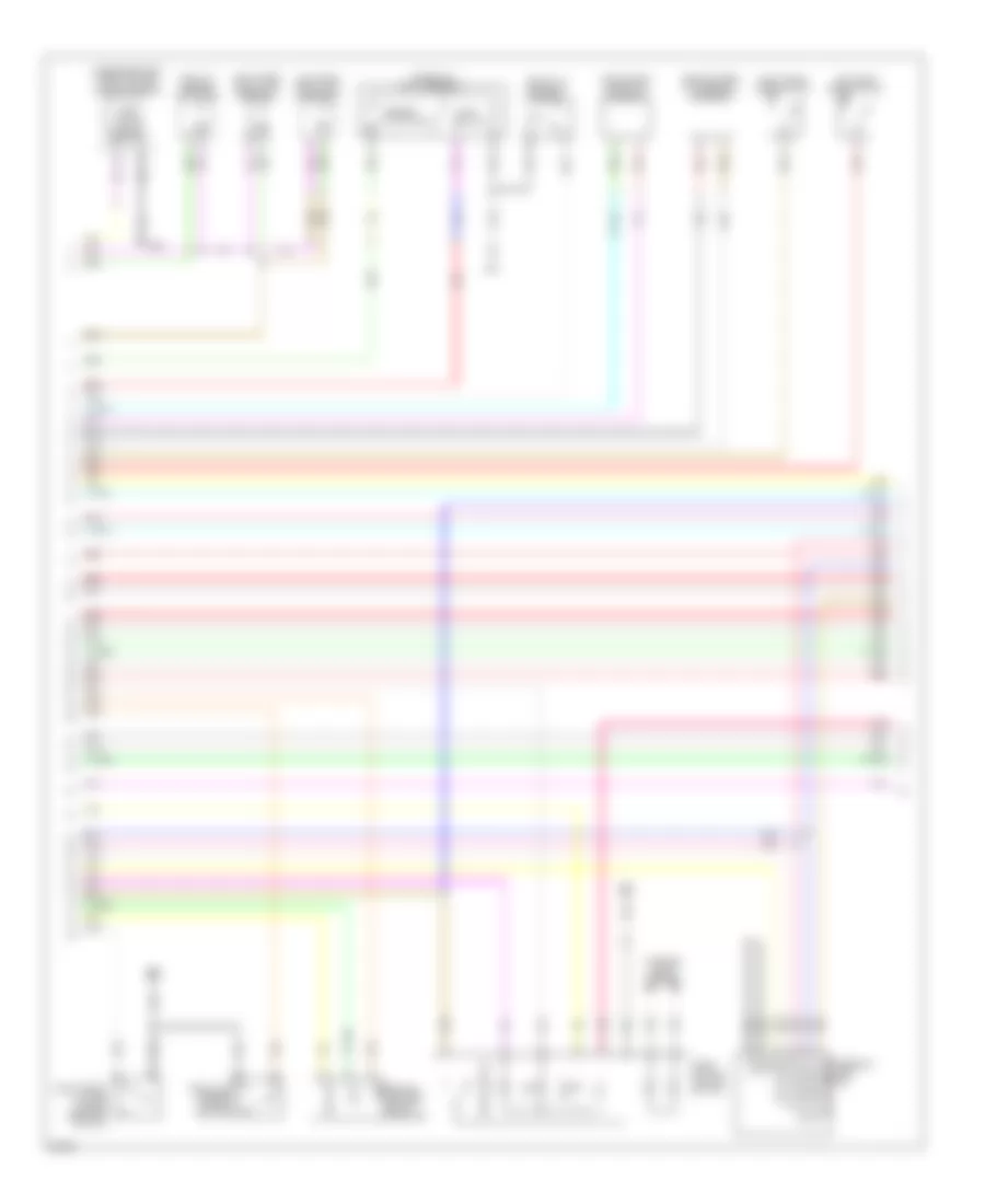
Anti-theft Wiring Diagram, Sedan (1 of 4) for Infiniti G35 x 2007

List of elements for Anti-theft Wiring Diagram, Sedan (1 of 4) for Infiniti G35 x 2007:
- (a/t)
- (m/t)
- A/t device
- Acc led
- As dr ant+
- As dr ant-
- As request sw
- Back anti+
- Back anti-
- Bat (f/l)
- Bat (fuse)
- Bat saver out
- Between full stroke & n
- Body control module (bcm)
- Buzzer
- Can-h
- Can-l
- Clutch sw
- Computer data lines system
- Console inside key antenna
- Door lock & unlock switch
- Door lock actuator
- Dr condition sw
- Dr lock out (all)
- Dr request sw
- Dr sw (as)
- Dr sw (drv)
- Dr sw (rr lh)
- Dr sw (rr rh)
- Dr unlock out (as)
- Dr unlock out (drv)
- Dr unlock out (rr)
- Driver side front door lock assembly
- Drv dr ant+
- Drv dr ant-
- Engine sw
- Exterior lights system
- Full stroke
- Fuse, fusible link & relay box
- Fusible link k 40a
- Gnd
- Hot at all times
- Immo ant ctrl
- Immo ant sig
- Ing usm cont1
- Instrument center inside key antenna
- Interior lights system
- Key cylinder switch
- Key slot ill
- Key sw sig
- Keyless tuner sig
- Left front outside handle (request switch)
- Left front outside handle key antenna
- Lf fr flshr out
- Lock
- Lock led
- Lr flshr out
- M11
- M118
- M119
- M120
- M121
- M122
- M123
- M95
- On led
- Passenger side front door lock assembly
- Pnk
- Power window main switch
- Power windows system
- Pwr wdw serial link
- Red
- Rh fr flshr out
- Right front outside handle key antenna
- Room ant1+
- Room ant1-
- Room ant2+
- Room ant2-
- Room lamp out
- Rr flshr out
- S/l (k line)
- S/l 12v (cpu)
- S/l condition 1
- S/l condition 2
- Security ind out
- Sensor gnd
- Shift n/p
- Shift p
- St cont usm
- Stop lamp high
- Stop lamp low
- Trunk anti+
- Trunk anti-
- Trunk cancel sw
- Trunk opener out
- Trunk request sw
- Trunk sw
- Unlock
- Unlock sensor
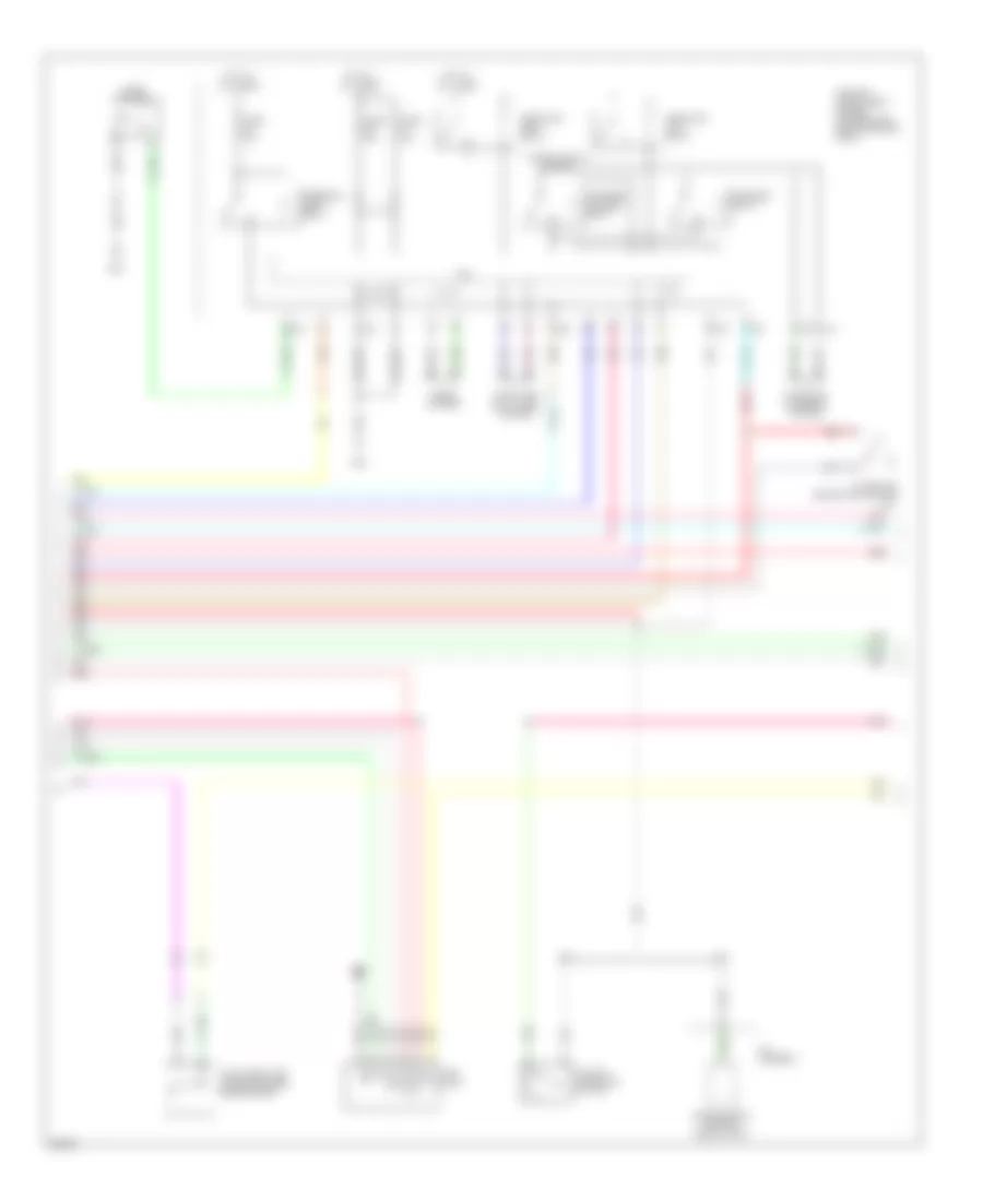
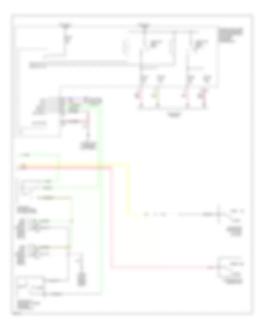
Anti-theft Wiring Diagram, Sedan (2 of 4) for Infiniti G35 x 2007
List of elements for Anti-theft Wiring Diagram, Sedan (2 of 4) for Infiniti G35 x 2007:
- Acc
- B61
- Batt
- Door lock & unlock switch
- Fuel lid opener actuator
- Gnd
- Ill
- Interior lights system
- Lamp switch
- Left rear door lock assembly
- Left rear door switch
- Lock
- M95
- Opener actuator
- Passenger side front power window switch
- Pnk
- Push switch
- Push- button ignition switch
- Rear bumper outside key antenna
- Red
- Remote keyless entry receiver
- Right front outside handle (request switch)
- Right rear door lock assembly
- Right rear door switch
- S/l (k line)
- S/l 12v (cpu)
- S/l 12v (mech) steering lock unit
- S/l condition 1
- S/l condition 2
- Sig out
- Trunk lid lock assembly
- Trunk lid opener cancel switch
- Trunk lid request switch
- Trunk room inside key antenna
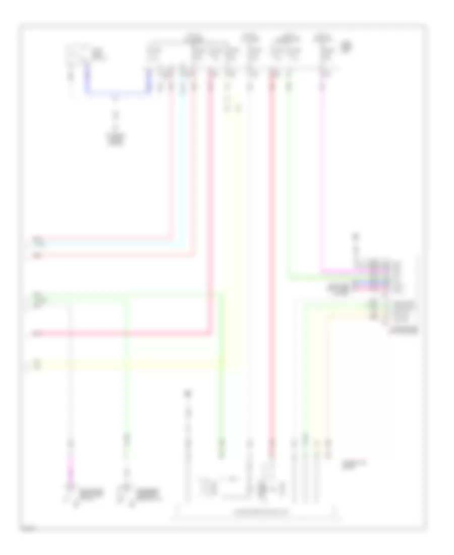
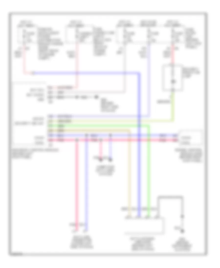
Anti-theft Wiring Diagram, Sedan (3 of 4) for Infiniti G35 x 2007
List of elements for Anti-theft Wiring Diagram, Sedan (3 of 4) for Infiniti G35 x 2007:
- A/t
- A/t assembly
- A/t device (detection switch) (a/t)
- Bat
- Clock
- Clutch interlock switch
- Computer data lines system
- Cpu
- Data
- E22
- Fuse 10a
- Fuse 15a
- Gnd
- Headlamp high relay
- Headlamp low relay
- Headlights system
- Hood switch
- Horns system
- Hot at all times
- Ill
- Ill bat key slot
- Intelligent key warning buzzer (engine room)
- Ipdm e/r (intelligent power distribution module engine room)
- M/t
- M95
- Pnk
- Red
- Sig sw
- Starter control relay
- Starter relay
- Starting/ charging system
- Steering lock relay
- Transmission control module (tcm)
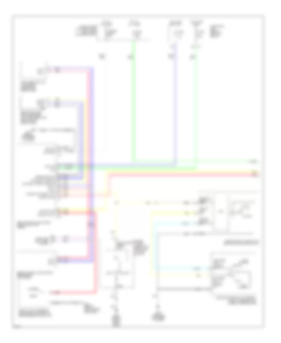
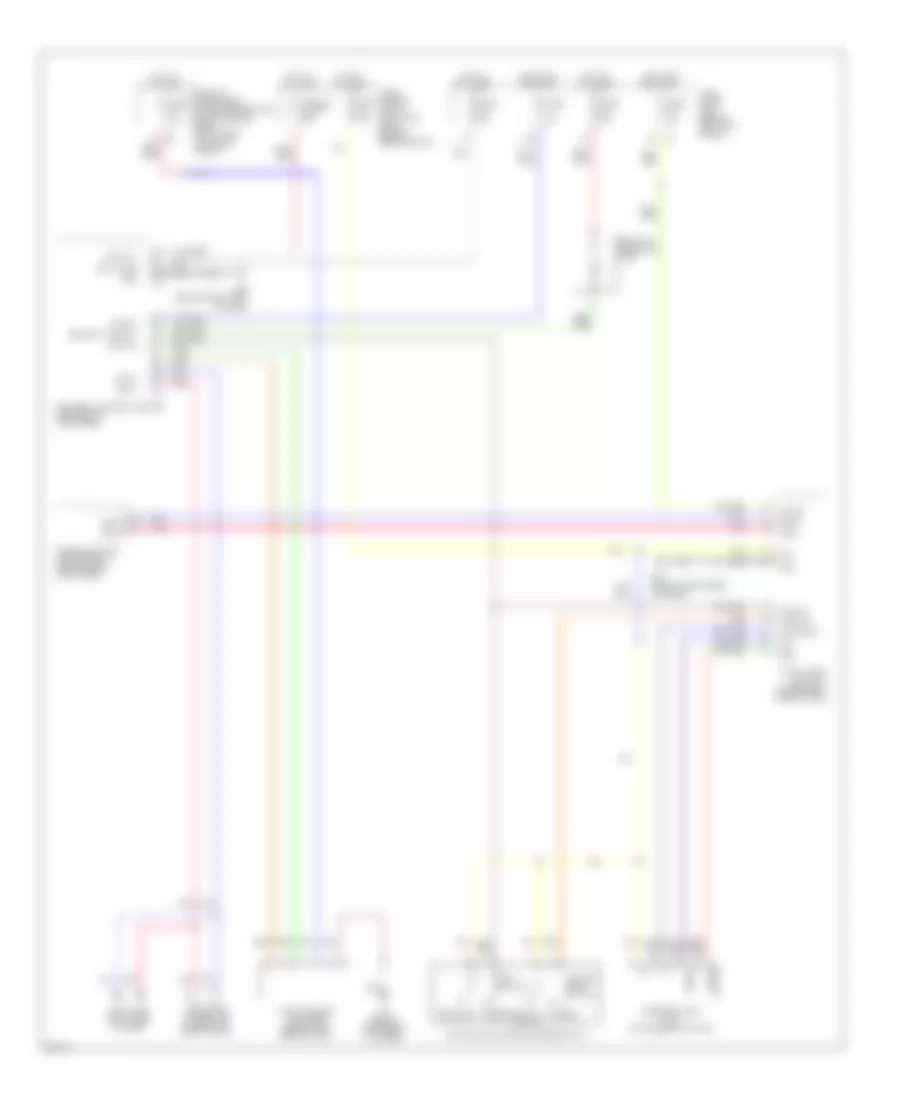
Anti-theft Wiring Diagram, Sedan (4 of 4) for Infiniti G35 x 2007
List of elements for Anti-theft Wiring Diagram, Sedan (4 of 4) for Infiniti G35 x 2007:
- 12c
- Acc
- Amp-lcd
- Amp-meter
- Buzzer
- Can-h
- Can-l
- Combination meter
- Computer data lines system
- Driver side front door switch
- E103
- Exterior lights system
- Fuse 10a
- Fuse block (j/b)
- Gnd
- Hot at all times
- Hot in acc or on
- Hot in on or start
- Ign
- Key ind
- Lcd-amp
- M11
- M66
- M67
- Meter-amp
- Passenger side front door switch
- Pnk
- Red
- Security ind
- Stop lamp switch
- Unified meter & a/c amplifier
- Unified meter control unit
Forced Entry Wiring Diagram, Coupe (1 of 2) for Infiniti G35 x 2007
List of elements for Forced Entry Wiring Diagram, Coupe (1 of 2) for Infiniti G35 x 2007:
- (behind instrument cluster)
- 12a
- 15a
- Acc
- B413 (behind right side of rear seat)
- Battery
- Between full stroke & n
- Body control module (bcm) (behind left kick panel)
- Can-h
- Can-l
- Closed
- Computer data lines system
- Cpu
- Door sw (as)
- Door sw (dr)
- Driver side door lock assembly (key cylinder switch) (in rear of driver door)
- Engine control module (ecm) (behind right kick panel)
- Full stroke
- Fuse 10a
- Fuse 15a
- Fuse block (j/b) (behind left kick panel)
- Fuse, fusible link & relay box (right rear of engine compt)
- Fusible link f 50a
- Gnd
- Ground
- Hot at all times
- Hot in acc or on
- Hot in on or start
- Ignition
- Intelligent key unit (if equipped) (under right side of dash)
- Key cyl lock sw
- Key cyl unlock sw
- Keyless tuner power sig
- Keyless tuner sig
- Lock
- M30
- M30 (behind instrument cluster)
- M66 (behind right side of dash)
- Open
- Pnk
- Power
- Power wdo serial link
- Power window main switch (door lock & unlock switch)
- Power window sub-switch (door lock & unlock switch)
- Pwr wdo serial link
- Pwr window serial link
- Red
- Remote keyless entry receiver (w/o intelligent key) (behind right side of dash)
- Sensor ground
- Signal
- Trunk lid lock assembly (trunk room lamp switch) (center rear of trunk lid)
- Trunk switch
- Unlock
Forced Entry Wiring Diagram, Coupe (2 of 2) for Infiniti G35 x 2007
List of elements for Forced Entry Wiring Diagram, Coupe (2 of 2) for Infiniti G35 x 2007:
- (on right side of engine compartment)
- Can-h
- Can-l
- Closed
- Computer data lines system
- Cpu
- Driver side door switch (at left "b" pillar)
- E17
- E32
- E33
- E35
- E36
- E43 (on left front side of engine compt)
- Fuse 10a
- Fuse 15a
- Gnd (power)
- Gnd (signal)
- Headlamp high
- Headlamp high relay
- Headlamp low
- Headlamp low relay
- Headlights system
- Hood sw
- Hood switch (left front corner of engine compartment)
- Horn (high) (right front of engine compt, behind grille)
- Horn (low) (right front of engine compt, behind grille)
- Horn relay (in fuse, fusible link & relay box)
- Horn rly
- Hot at all times
- Ipdm e/r (intelligent power distribution module engine room) (right rear of engine compartment)
- Open
- Passenger side door switch
- Pnk
- Red
Immobilizer Wiring Diagram (NATS), Coupe with Intelligent Key Unit for Infiniti G35 x 2007
List of elements for Immobilizer Wiring Diagram (NATS), Coupe with Intelligent Key Unit for Infiniti G35 x 2007:
- (behind instrument cluster)
- +12
- 15a
- 2a m4
- 5v output
- Bat
- Bat (f/l)
- Bat (fuse)
- Bcm (body control module) (behind left kick panel)
- Can-h
- Can-l
- Computer data lines system
- Data link connector (lower left side of dash)
- Drawn
- Earth
- Engine control module (ecm) (behind right kick panel)
- Fuse 10a
- Fuse 15a
- Fuse block (j/b) (behind left kick panel)
- Fuse, fusible link & relay box (right rear of engine compt)
- Fusible link f 50a
- Gnd
- Hot at all times
- Hot in on or start
- Ign sw
- Ignition knob switch
- Inserted removed
- Intelligent key unit (under right side of dash)
- Ipdm e/r (intelligent power distribution module engine room) (right rear of engine compt)
- Key sw
- Key switch
- Key switch & ignition knob switch
- M30
- M30 (behind instrument cluster)
- M66 (behind right side of dash)
- Nats antenna amplifier (behind left side of dash)
- Pnk
- Push sw
- Security ind out
- Security indicator lamp
- Sig
- Signal
- Steering lock unit (on steering column)
- With- pushed
Immobilizer Wiring Diagram (NATS), Coupe without Intelligent Key Unit for Infiniti G35 x 2007
List of elements for Immobilizer Wiring Diagram (NATS), Coupe without Intelligent Key Unit for Infiniti G35 x 2007:
- 15a
- 8a m4
- Bat (f/l)
- Bat (fuse)
- Bcm (body control module) (behind left kick panel)
- Can-h
- Can-l
- Computer data lines system
- Data link connector (lower left side of dash)
- Engine control module (ecm) (behind right kick panel)
- Fuse 10a
- Fuse 15a
- Fuse block (j/b) (behind left kick panel)
- Fuse, fusible link link & relay box (right rear of engine compt)
- Fusible link f 50a
- Gnd
- Hot at all times
- Hot in on or start
- Ign sw
- Ipdm e/r (intelligent power distribution module engine room) (right rear of engine compt)
- M30 (behind instrument cluster)
- M66 (behind right side of dash)
- Nats antenna amplifier (behind left side of dash)
- Pnk
- Security ind out
- Security indicator lamp