BODY CONTROL MODULES
Body Control Modules Wiring Diagram for Hyundai XG350 2004
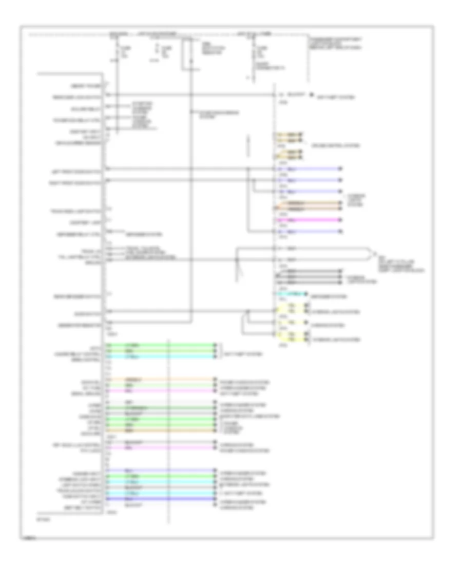
List of elements for Body Control Modules Wiring Diagram for Hyundai XG350 2004:
- Anti-theft system
- B/alarm relay
- Chime
- Code save
- Computer data lines system
- Courtesy lamp
- Cruise control system
- Data
- Defogger relay ctrl
- Defogger system
- Door switch
- Down (rl)
- Down (rr)
- Etacm
- Exterior lights system
- Fuse 10a
- G03 (on left "a" pillar, near passenger compt junction block)
- Generator resistor
- Ground
- Hazard relay control
- Hood switch input
- Hot at all times
- Hot in on
- Hot in on or start
- I/p-a
- I/p-b
- I/p-d
- I/p-e
- I/p-h
- I/p-j
- I/p-k
- I/p-m
- I/p-p
- Int (time)
- Int wiper
- Interior lights system
- Key hole illum control
- Left front door switch
- Light switch (park)
- M33-1
- M33-2
- M33-3
- Memory power
- On input
- On/start input
- P/w (lock)
- Passenger compartment junction block (behind left end of dash)
- Power wdo relay ctrl
- Power windows system
- Pre- excitation resistor
- Rear defogger switch
- Rear door lock switch
- Right front door switch
- Seat belt switch
- Short connector "a"
- Signal ground
- Siren control
- Starting/ charging system
- Starting/charging system
- Steering lock input
- Tail lamp relay ctrl
- Trunk lid
- Trunk room lamp switch
- Trunk unlock switch
- Trunk, tailgate, fuel doors system
- Up (rl)
- Up (rr)
- Vehicle speed sensor
- Warning system
- Washer input
- Wiper
- Wiper/washer system
 English