CRUISE CONTROL
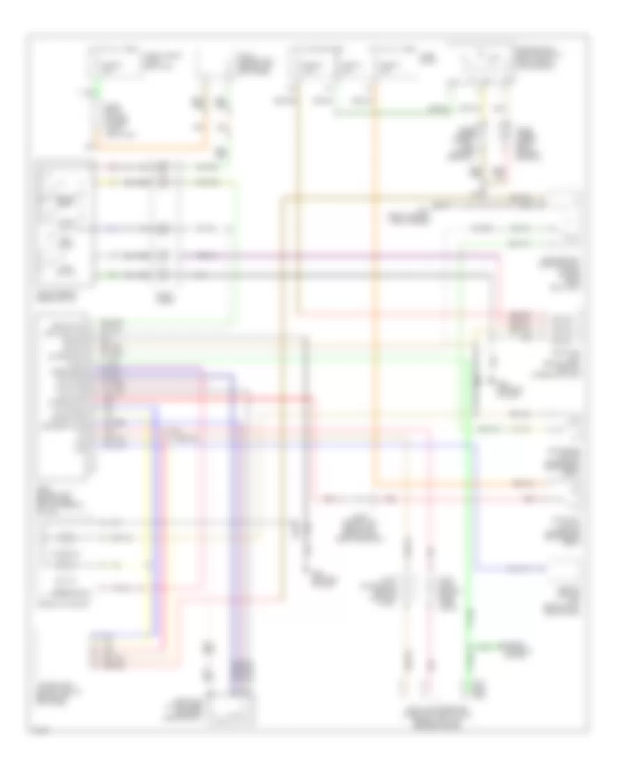
Cruise Control Wiring Diagram for Infiniti Q45 t 1999
List of elements for Cruise Control Wiring Diagram for Infiniti Q45 t 1999:
- (1999)
- (2000)
- (2001)
- 13h
- 17b
- Abs/tcs control unit (behind right side of dash)
- Air valve
- Ascd brake switch (on bracket, above brake pedal)
- Ascd control unit (behind dash, left of steering column)
- Ascd hold unit (behind dash, right of steering column)
- Ascd pump (at left rear corner of engine compt)
- Ascd steering wheel switch
- Cancel
- Clock
- Combination meter
- Cruise ind
- Cruise lamp
- Data link connector (under left side of dash, beside hood lock release handle)
- Diode (under carpet, near driver's door sill)
- Engine controls system
- Fuse 18 10a
- Fuse 32 7.5a
- Fuse 37 15a
- Fuse 64 15a
- Fuse block
- Fuse, fusible link & relay box
- G101 (front of right front fender)
- G202 (left end of dash)
- Ground
- Horn relay (in fuse, fusible link & relay box)
- Hot at all times
- Hot in on or start
- Ignition
- Joint conn- ector 2 (near fuse block)
- Joint connector 1 (behind left side of dash, near fuse block)
- Joint connector 7 (behind left kick panel)
- Joint connector 8 (behind left kick panel)
- Main out
- Main sw
- Main switch
- Nc brake sw
- Nca
- No brake sw
- O/d cancel
- Park/neutral position relay (in fuse, fusible link & relay box)
- Park/neutral position switch (right side of transmission)
- Pnk
- Pump pwr
- Red
- Release valve
- Res/acc sw
- Resume/ accel
- Set ind
- Set/ coast
- Set/coast sw
- Speed sens
- Speed sig out
- Spiral cable
- Stoplight switch (on bracket above brake pedal)
- Tcs
- Transmission control module (behind left kick panel)
- Vac motor
 English