ELECTRONIC POWER STEERING
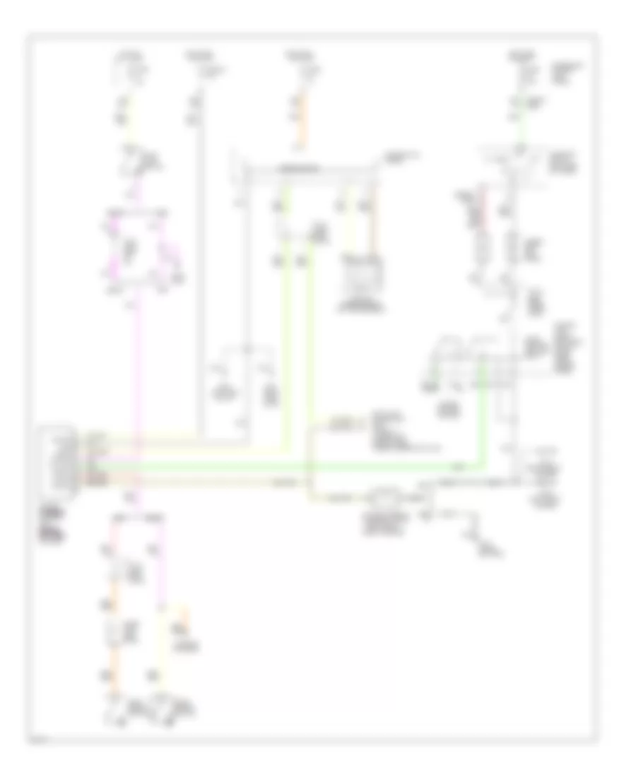
Electronic Power Steering Wiring Diagram for Infiniti J30 1995
List of elements for Electronic Power Steering Wiring Diagram for Infiniti J30 1995:
- (1996-97) (1995)
- (left front
- (left rear wheel- well)
- (left side of i/p)
- (right front
- (right side of i/p)
- 1996-
- 1996-97
- 2-1
- A25 c1
- A26 c2
- A39 d11
- All times
- Combination meter
- Cruise control system
- Data link connector for consult (under left side of dash, under steering column)
- Diode (left side of i/p)
- Diodes (left kick panel)
- Fender)
- Fuse 15a
- Fuse 32 7.5a
- Fuse 7.5
- Fuse 7.5a
- Fuse block (on left kick panel)
- Fusible link, fuse & relay box (in left front inner fender panel)
- G100
- G101
- G111 (near battery)
- G15 t8
- G201
- G202
- Gnd
- Hot at
- Hot in on
- Hot in on or start
- Ign sw
- Inhibit
- Inhibitor switch (left side of trans)
- J/c 12
- J/c 6 (left side of i/p)
- J/c 7 (left side of i/p)
- Or start
- Park brake switch
- Park/ neutral position relay
- Pb sw
- Power steering solenoid valve
- Power steering steering steering steering control unit (behind (behind (behind (behind left side left side left side left side of dash)
- Ps sol
- Side of engine)
- Speedometer
- Stop lamp
- Stop lamp switch
- Stp sw
- V sens
- Vehicle speed sensor (on transmission)
- Warning systems
 English