ENGINE PERFORMANCE
2.3L
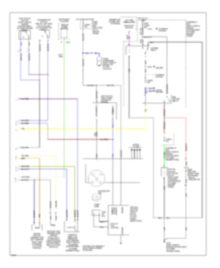
2.3L, Engine Performance Wiring Diagrams (1 of 2) for Isuzu Pickup S 1995

List of elements for 2.3L, Engine Performance Wiring Diagrams (1 of 2) for Isuzu Pickup S 1995:
- "check engine" malfunction indicator lamp (mil)
- (left side of engine compartment, on inner fender panel)
- (right side of engine compartment, on inner fender panel)
- (top center of engine, on rear of carburetor)
- A/c on input
- Air conditioning system
- Air inj react vsv cont
- Air management valve (amv)
- C213
- C214
- C221
- C222
- C274
- C275
- Dash fuse box (left side of i/p, behind panel)
- Data link connector (dlc) (below left side of i/p, at kick panel)
- Diagnostic trouble code (dtc) terminal (below left side of i/p, at kick panel)
- Dlc/dtc input
- Duty sol control
- Duty solenoid (top center of engine, in front of carburetor)
- Dwell lead (right side of engine compartment, taped to harness)
- Ect sensor input
- Efe heater relay cont
- Egr vsv control
- Engine control module (ecm) (below left side of i/p, at kick panel)
- Engine control module (ecm) relay
- Engine rpm input
- Evap cnstr purge vsv
- Evaporative emission canister purge vacuum switching valve (right side of engine compartment, on inner fender panel)
- Exhaust gas recirculation (egr) vacuum switching valve (calif only)
- Exhaust gas temp sen
- Fuse 1 10a
- Fuse 3 10a
- Fuse 7 10a
- Fuse 8 10a
- Fuse/relay box (right side of engine compartment, on inner fender panel)
- G101 (right side of engine compartment, on inner fender panel)
- G104 (left rear corner of engine compartment, on inner fender panel)
- G131 (right side of engine, on intake manifold)
- Ground
- Hot at all times
- Hot in on or start
- Idle vacuum switch in
- Ignition input
- Instrument cluster
- Manifold absolute pressure (map) vacuum switching valve
- Map sensor input
- Map vsv control
- Mil control
- Oxygen sensor (lower left side of engine, in exhaust manifold)
- Oxygen sensor input
- Power input
- Ref voltage
- Slow cut sol control
- Slow cut solenoid
- Vss input
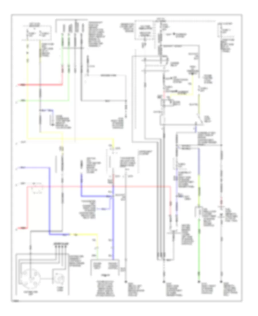
2.3L, Engine Performance Wiring Diagrams (2 of 2) for Isuzu Pickup S 1995
List of elements for 2.3L, Engine Performance Wiring Diagrams (2 of 2) for Isuzu Pickup S 1995:
- (right side of engine, in intake manifold)
- Accelerator switch (below left side of i/p, on top of accelerator pedal)
- C274
- Charge relay
- Charging system
- Choke heater
- Dash fuse box (left side of i/p, behind panel)
- Distributor assembly (right rear corner of engine)
- Distributor cap
- Efe heater (right side of engine, below caburetor)
- Efe heater relay
- Engine coolant temperature (ect) sensor
- Exhaust gas temperature sensor (calif. only) (lower right side of engine compartment, below intake manifold)
- Fuse 2 10a
- Fuse 6 10a
- Fuse 9 15a
- Fuse/relay box (right side of engine compartment, on inner fender panel)
- Fuse/relay box (right side of engine compartment, on inner fender panel)
- G105 (right side of engine compartment, on inner fender panel)
- Generator (lower left of engine)
- Ground
- Heater
- Hot at all times
- Hot in on or start
- Idle vacuum switch (right side of engine compartment, on inner fender panel)
- Ignition coil (right rear corner of engine)
- Ignition control module solid- state: do not check resistance
- Ignition vacuum switching valve (right side of engine compartment on inner fender panel)
- Indicator control
- Instrument cluster
- Main fuse 1 60a
- Manifold absolute pressure (map) sensor (right side of of engine compartment, on inner fender panel)
- Nca
- Noise condenser (right side of engine, on intake manifold)
- Pick- up coil
- Pick-up coil control
- Power
- Primary
- Primary output control
- Secondary
- Spark plugs
- Timer core
- Vehicle speed sensor
- Voltage regulator
- Wire coil
2.6L
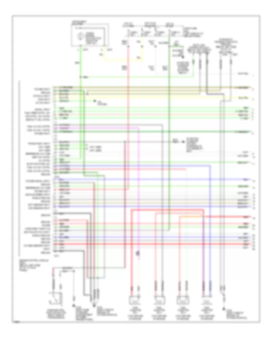
2.6L, Engine Performance Wiring Diagrams (1 of 3) for Isuzu Pickup S 1995
List of elements for 2.6L, Engine Performance Wiring Diagrams (1 of 3) for Isuzu Pickup S 1995:
- "check engine" malfunction indicator lamp (mil)
- (top center of engine)
- A/c on input
- A/c system
- A/t only
- Air cntrl vsv cntrl
- C207
- C208
- C210
- C211
- C274
- C275
- Dash fuse box (left side of i/p, behind panel)
- Data link connector (dlc) (below left side of i/p, at kick panel)
- Diagnostic trouble code (dtc) terminal (below left side of i/p, at kick panel)
- Dtc/dlc input
- Ect sensor input
- Egr duty sol cntrl
- Egr vsv cntrl
- Engine control module (ecm) (below left side of i/p, at kick panel)
- Evap can purg vsv
- Fuel inj no.1 cntrl
- Fuel inj no.2 cntrl
- Fuel inj no.3 cntrl
- Fuel inj no.4 cntrl
- Fuel injector no.1
- Fuel injector no.2
- Fuel injector no.3
- Fuel injector no.4
- Fuel pres cntrl vsv
- Fuse 12 10a
- Fuse 3 10a
- Fuse 7 10a
- Fuse 8 10a
- G105 (right side of engine compartment on inner fender panel)
- G120 (right side of engine, on intake manifold)
- Ground
- Hot at all times
- Hot in on or start
- Hot in start
- Idle input
- Ignition switch input
- Input
- Instrument cluster
- Map sensor input
- Mil cntrl
- Not used
- Oxygen sensor input
- Park/neutral position switch (right side of transmission)
- Power
- Power input
- Power signal input
- Red
- Reference voltage
- Shield ground
- Signal input
- Starting/ charging system (diode box b, in fuse/relay box)
- Starting/ charging system (starter relay)
- Trans posit input
- Vehicle speed input
- Wide open throttle
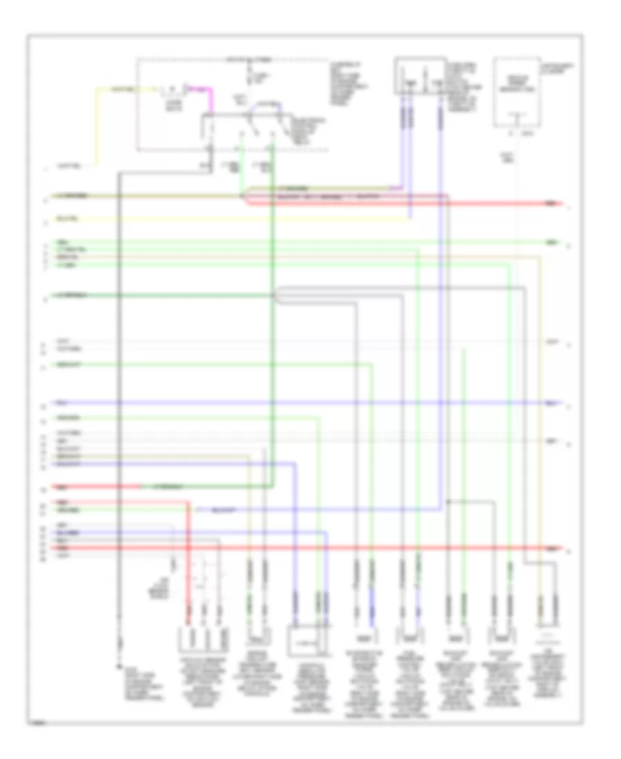
2.6L, Engine Performance Wiring Diagrams (2 of 3) for Isuzu Pickup S 1995
List of elements for 2.6L, Engine Performance Wiring Diagrams (2 of 3) for Isuzu Pickup S 1995:
- (lower right side of engine, below intake manifold)
- (right side of engine compartment, on inner fender panel)
- (top center rear of engine on valve cover)
- (top center rear of engine, on valve cover)
- Air flow sensor (solid state: do not measure resistance) (left front of engine compartment, on air flow sensor)
- Air flow sensor shield
- Air management valve (amv) (left front of engine compartment, right of airflow assembly)
- C274
- Cluster
- Diode box b
- Electronic control module (ecm) relay
- Engine coolant temperature (ect) sensor
- Evaporative emission canister purge vacuum switching valve
- Exhaust gas recirculation (egr) duty solenoid (calif. only)
- Exhaust gas recirculation (egr) vacuum switching valve (calif. only)
- Fuel pressure control valve vacuum switching valve
- Fuse 1 15a
- Fuse/relay box (right side of engine compartment, on inner fender panel)
- G105 (right side of engine compartment, on inner fender panel)
- Ground
- Hot at all times
- Idle
- Instrument
- Manifold absolute pressure (map) sensor (right side of engine compartment, on inner fender panel)
- Output
- Power
- Red
- Vehicle speed sensor (vss)
- Wide open throttle (wot) switch (top center rear of engine, on throttle assembly)
- Wot
2.6L, Engine Performance Wiring Diagrams (3 of 3) for Isuzu Pickup S 1995
List of elements for 2.6L, Engine Performance Wiring Diagrams (3 of 3) for Isuzu Pickup S 1995:
- (not used)
- Air conditioning system
- Air regulator (lower right rear of engine, below intake manifold)
- Braided wire
- C134
- C274
- C275
- Charge relay
- Charging system
- Coil wire
- Crankshaft position sensor (solid state: do not check resistance) (right rear of engine, in bottom of distributer assembly)
- Dash fuse box (left side of i/p, behind panel)
- Diode box a
- Distributer assembly (top right rear corner of engine)
- Distributer cap
- From oil pressure switch
- Fuel pump (beneath truck bed, in top of fuel tank)
- Fuel pump relay
- Fuse 11 20a
- Fuse 2 20a
- Fuse 6 10a
- Fuse 7 10a
- Fuse 9 15a
- Fuse/relay box (right side of engine compartment, on inner fender panel)
- Fuse/relay box (right side of engine compartment, on inner fender panel)
- G105 (right side of engine compartment, on inner fender panel)
- G119 (right front of engine, on intake manifold)
- G120 (right side of engine on intake manifold)
- G202 (below left side of i/p behind engine control module)
- G409 (beneath truck bed on rear of right frame rail)
- Generator (lower left front of engine)
- Ground
- Heated oxygen sensor (ho2s) (lower left side of engine, in exhaust manifold)
- Hot at all times
- Hot in on or start
- Hot in start
- Ignition coil (top center rear of engine, on valve cover)
- Indicator control
- Instrument cluster
- Main fuse 1 60a
- Nca
- Noise condensor (top center rear of engine, on valve cover)
- Power
- Power distrib- ution system
- Power signal input
- Power switch (solid state: do not check resistance) (right side of engine, below intake manifold)
- Primary
- Primary winding control
- Red
- Reference voltage
- Secondary
- Signal output
- Spark plugs
- Tachometer (solid-state: do not check resistance)
- Tachometer test connector (right side of engine compartment, behind fuse/ relay box)
- Timer core
- Voltage regulator