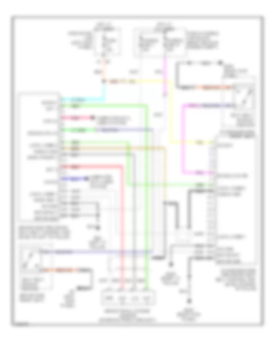
PASSIVE RESTRAINTS
Passive Restraints Wiring Diagram for Infiniti FX35 2010
List of elements for Passive Restraints Wiring Diagram for Infiniti FX35 2010:
- 1a m1
- B202 (right kick panel)
- B224 (right "c" pillar)
- B24 (left "c" pillar)
- B7 (left kick panel)
- Brake pedal stroke sensor (on brake pedal bracket)
- Buckle sw lh
- Buckle sw rh
- Can hi
- Can lo
- Computer data lines system
- Driver side front seat
- Driver side pre-crash seat belt control unit (base of left "b" pillar)
- Fuse & fusible link block (right rear of engine compt)
- Fuse 10a
- Fuse block (j/b) (left kick panel)
- Fusible link j 30a
- Fusible link k 30a
- Gnd
- Hot at all times
- Local comm 1
- Local comm 2
- Motor bat
- Motor gnd
- Nca
- Out
- Out 1
- Out 2
- Passenger side front seat
- Passenger side pre-crash seat belt control unit (base of right "b" pillar)
- Pnk
- Red
- Seat belt buckle switch
- Sens gnd 1
- Sens power 1
- Shield gnd
- Sig bat
- Sig gnd
- Vcc
 English