POWER DISTRIBUTION
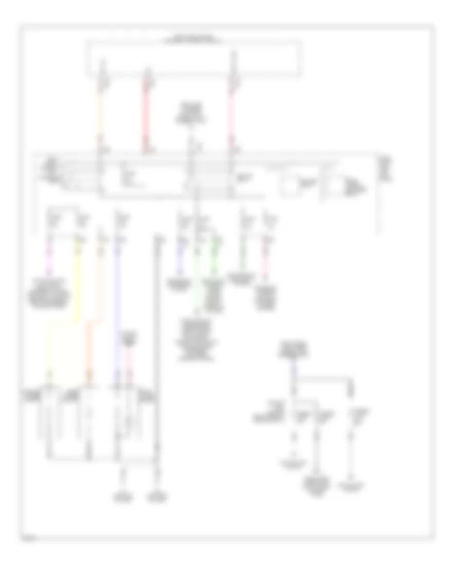
Power Distribution Wiring Diagram (1 of 3) for Infiniti FX35 2010

List of elements for Power Distribution Wiring Diagram (1 of 3) for Infiniti FX35 2010:
- (left kick panel) fuse block (j/b)
- (option connector)
- (right side of dash) m95
- 12g
- Acc ind
- Acc rly
- Accessory relay 2 (right side of dash)
- Anti-lock brakes system
- Anti-theft system
- B224 (right "c" pillar)
- Battery
- Bcm (body control module) (right end of dash)
- Body computer system
- Body computer, electronic suspension & seats systems
- Body computer, seats, interior lights & memory systems
- Cpu
- D nca
- E101
- E103
- Electronic power steering system
- Engine controls system
- Exterior lights & cruise control systems
- Fuse & fusible link block (right rear of engine compt)
- Fuse 10a
- Fuse 15a
- Fuse 20a
- Fuse 30a
- Fusible link a 250a
- Fusible link b 100a
- Fusible link c 100a
- Fusible link d 80a
- Fusible link e 100a
- Fusible link f 60a
- Fusible link g 50a
- Fusible link h 30a
- Fusible link holder (right rear of engine compt)
- Fusible link j 30a
- Fusible link k 30a
- Fusible link l 40a
- Fusible link m 30a
- Fusible link n 50a
- Horns & starting/ charging systems
- Horns system
- Instrument cluster, door locks, anti-theft, computer data lines, air conditioning, wiper/washer, warning & mirrors systems
- Interior lights system
- Ipdm e/r (intelligent power distribution module engine room) (right rear of engine compt)
- Lock ind
- Luggage room power socket
- M11 (left end of dash)
- M119
- M122
- M123
- Navigation & sound systems
- Nca
- On ind
- Passive restraint system
- Pnk
- Push button ignition switch
- Push sw
- Push switch
- Red
- Seats system
- Sound systems
- Starting/ charging system
- To (ipdm e/r) ecm relay (diagram 3 of 3)
- To (ipdm e/r) fuse 58 (diagram 3 of 3)
- To (ipdm e/r) starter relay (diagram 3 of 3)
- To accessory relay (diagram 2 of 3)
- To fuse block (j/b) iginition relay (diagram 2 of 3)
- To fusible link holder fusible link p (diagram 2 of 3)
- To fusible link holder fusible link s (diagram 2 of 3)
- Transmissions & cruise control systems
- Transmissions system
- Trunk, tailgate, fuel doors systems
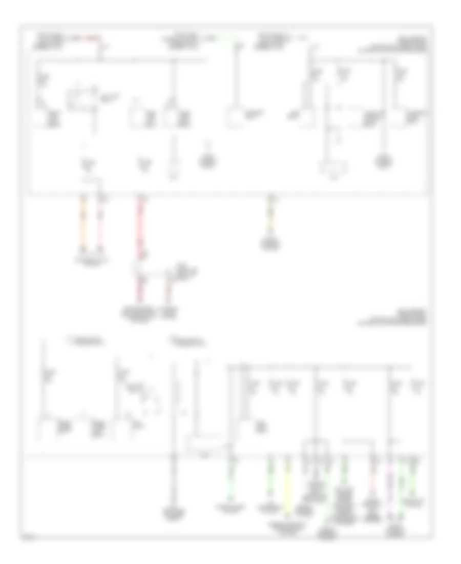
Power Distribution Wiring Diagram (2 of 3) for Infiniti FX35 2010
List of elements for Power Distribution Wiring Diagram (2 of 3) for Infiniti FX35 2010:
- (right end of dash) bcm (body control module)
- (right rear of engine compt)
- 10f
- 11c
- 12c
- Acc rly
- Accessory relay
- Air conditioning, anti-theft, interior lights, instrument cluster, mirrors, navigation, body computers & sound systems
- Bat
- Blower relay
- Computer data lines system, transmissions, seats, sound, navigation, warning, headlights, air conditioning, instrument cluster & mirrors systems
- Console power socket
- Cooling fans system
- E102
- E103
- Electronic suspension system
- From fuse & fusible link block fuse 61 (diagram 1 of 3)
- From fuse & fusible link block fusible link h (diagram 1 of 3)
- From fuse 5 e (diagram 1 of 3)
- From fusible link holder fusible link b (diagram 1 of 3)
- Front power socket
- Fuse 10a
- Fuse 15a
- Fuse block (j/b) (left kick panel)
- Fusible link holder
- Fusible link o 50a
- Fusible link p 50a
- Fusible link s (5.0l) 50a
- Headlights, exterior lights, cruise control, & shift interlock systems
- Ign rly (f/b)
- Ignition relay
- Interior lights system
- M11 (left end of dash)
- M119
- M122
- M55 (left side of dash)
- Navigation, exterior lights & instrument cluster systems
- Nca
- Pnk
- Rear power socket
- Rear window defogger relay
- Red
Power Distribution Wiring Diagram (3 of 3) for Infiniti FX35 2010
List of elements for Power Distribution Wiring Diagram (3 of 3) for Infiniti FX35 2010:
- (right rear of engine compt) ipdm e/r (intelligent power distribution module engine room)
- A/c relay
- Air conditioning system
- Anti-lock brakes, cruise control, electronic power steering & transmissions systems
- Cpu
- Cruise control & anti- lock brakes systems
- E103
- E22 (right side of engine compt)
- Ecm relay
- Engine controls & transmissions systems
- Engine controls system
- Exterior lights system
- From fuse & fusible link block g fusible link h (diagram 1 of 3)
- From fuse 48 (diagram 3 of 3)
- From fuse 58 (diagram 3 of 3)
- From fusible link holder a
- From fusible link holder b
- Front fog lamp relay
- Front wiper high relay
- Front wiper relay
- Fuel pump relay
- Fuse 10a
- Fuse 15a
- Fuse 30a
- Fuse block (j/b) (left kick panel) b6
- Fusible link d (diagram 1 of 3)
- Fusible link f (diagram 1 of 3)
- Head lamp high relay
- Head lamp low relay
- Headlights system
- Ignition relay
- Interior lights & body computer systems
- Pnk
- Red
- Sound system, shift interlock & interior lights systems
- Starter relay
- Steering lock relay
- Tail-lamp relay
- Throttle control motor relay
- To fuse 49 (diagram 3 of 3)
- To fuse 60 (diagram 3 of 3)
- Wiper/washer system