SHIFT INTERLOCK
Electric Parking Brake Wiring Diagram for Hyundai Equus Ultimate 2013

List of elements for Electric Parking Brake Wiring Diagram for Hyundai Equus Ultimate 2013:
- (left side of dash) ipm
- (top left
- B-can transceiver
- Body unit-2 fuse 10a
- Box
- Brake fluid level sensor (on brake fluid reservoir)
- C-can high
- C-can low
- C-can transceiver
- Cluster fuse 10a
- Computer data lines system
- Connector
- E/r junction box (right rear of engine compt)
- E/r-e2b
- Ef31
- Em31
- Epb
- Epb control module (left rear suspension)
- Epb ind
- Epb-1 fuse 15a
- Epb-2 fuse 15a
- Ff02
- Ge03 (left front of engine compt)
- Gf08 (behind right side of rear seat)
- Ground
- High
- Hot at all times
- Hot in on or start
- I/p-lhe
- I/p-lhg
- Ill
- Instrument cluster
- Interior
- Je02
- Joint
- Joint connector jf01 (base of left "c" pillar)
- Left i/p junction
- Lights system
- Low
- M11-a
- M11-b
- M40-b
- Memory power
- Mf11
- Mf21
- Micom
- Mm02
- On/start in
- Parking brake ind
- Parking brk sw
- Pnk
- Shift resistor
- Side of dash)
- Sw 1
- Sw 2
- Sw 4
- Sw 5
- Switch
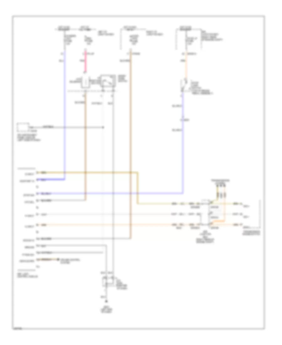
Shift & Key Lock Wiring Diagram for Hyundai Equus Ultimate 2013
List of elements for Shift & Key Lock Wiring Diagram for Hyundai Equus Ultimate 2013:
- "p" position switch
- A/con (acc) fuse 10a
- Acc/on in
- Atm sol
- Atm solenoid
- Chassis unit fuse 10a
- Cruise control system
- D input
- E/r junction box (right rear of engine compt)
- E/r-ca
- E/r-cb
- E/r-e1a
- E/r-e2a
- E/r-e2b
- Em21
- Gm01 (left end of dash)
- Ground
- Hot at all times
- Hot in acc or on
- Hot in on or start
- I/p-lhf
- I/p-rhb
- Ipm (instrument panel module) (left side of dash)
- J/c jm05 (center of dash)
- Key lock control module
- Left i/p junction box
- M40-b
- N input
- On/start in
- P input
- P posi sw
- Pnk
- Rdm fuse 10a
- Right i/p junction box
- Sig 1
- Sig 3
- Sig 4
- Sport mode switch
- Stop lamp switch (top of brake pedal assembly)
- Stop lp fuse 10a
- Stop sig
- Transmission range switch
- Transmissions system
- Vehicle spd