STARTING/CHARGING
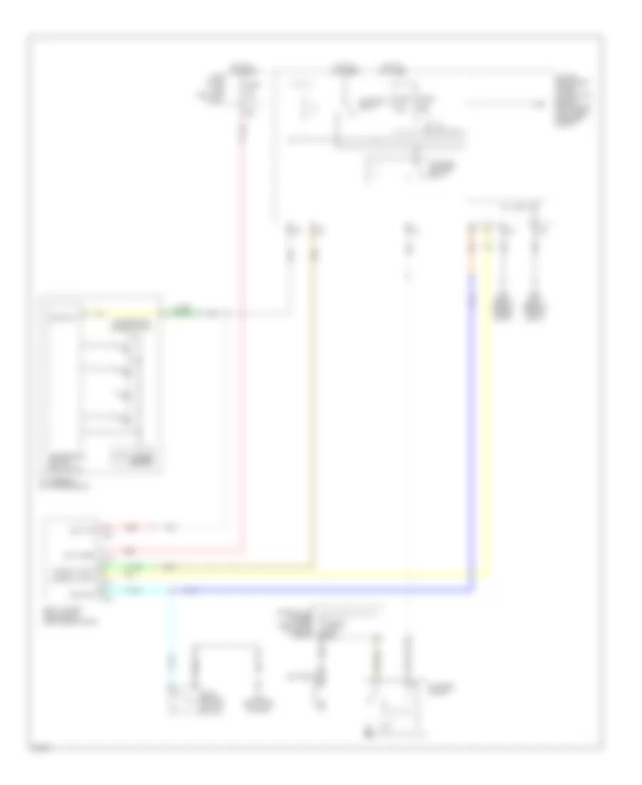
Charging Wiring Diagram for Infiniti FX35 2010

List of elements for Charging Wiring Diagram for Infiniti FX35 2010:
- (or pnk)
- 12c
- Alternator
- Battery
- Charge ind
- Combination meter
- Computer data lines system
- Cpu
- Fuse & fusible link block (right rear of engine compt)
- Fuse 10a
- Fuse 15a
- Fuse block (j/b) (left kick panel)
- Fusible link a 250a
- Fusible link c 100a
- Fusible link holder (right rear of engine compt)
- Horn relay 1 (in fuse & fusible link block)
- Hot in on or start
- Ipdm e/r (intelligent power distribution module engine room) (right rear of engine compt)
- Nca
- Pnk
- Red
Starting Wiring Diagram for Infiniti FX35 2010
List of elements for Starting Wiring Diagram for Infiniti FX35 2010:
- (or red)
- A/t assembly (on transmission)
- Bat (fuse)
- Battery
- Body control module (bcm) (right end of dash)
- Cpu
- E22 (right side of engine compt)
- E46 (left rear of engine compt)
- Fuse 10a
- Fuse 15a
- Fuse block (j/b) (left kick panel)
- Fusible link a 250a
- Fusible link holder (right rear of engine compt)
- Hot at all times
- Ign relay cont
- Ipdm e/r (intelligent power distribution module engine room) (right rear of engine compt)
- M119
- M121
- M122
- M123
- M95 (right side of dash)
- Nca
- Output speed sensor
- Push button ignition switch
- Push sw
- Red
- Shift n/p
- St relay cont
- Start rly
- Starter control relay
- Starter motor
- Starter relay
- Sw1
- Sw2
- Sw3
- Sw4
- Transmission control module (tcm)
- Transmission range switch