TRANSMISSION
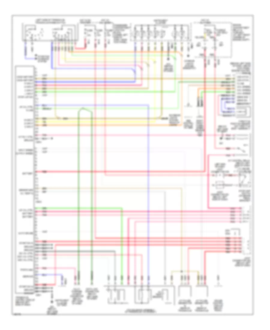
A/T Wiring Diagram for Hyundai Elantra GT 2002
List of elements for A/T Wiring Diagram for Hyundai Elantra GT 2002:
- (behind left side of dash, above kick panel) engine control module
- (below
- (left end of dash) joint connector m36
- (left side of transaxle) transaxle range switch
- 2 input
- 2nd val ctrl
- 3 input
- A/t control relay (below left side of dash)
- A/t pulse generator a (rear of transaxle)
- A/t pulse generator b (rear of transaxle)
- A/t rly ctrl
- Abs control module (w/ abs)
- Atm solenoid assembly (in transaxle valve body)
- Auto cruise
- Battery
- C86-1
- C86-2
- C86-3
- Com ntwk
- Comm netwrk
- Cruise control module (below radio)
- D input
- Data link connector (below
- Dcc val ctrl
- Ec03
- Ec04
- Ecu fuse 10a
- Engine compartment relay & fuse box (at left front corner of engine compt)
- Exterior lights system (back-up lamps)
- Fuse 10a
- Fuse 15a
- Fusible link (ecu) 20a
- G14 (behind center of dash)
- G21
- G21 (below left side of dash)
- Gear sig
- Ground
- Hot at all times
- Hot in on or start
- I/p-h
- I/p-j
- Input speed
- Instrument cluster
- Instrument cluster (w/ trip)
- Interior lights system (rheostat)
- J/c e57
- J/c e62
- Joint connector c91 (below left side of dash)
- Joint connector c92 (below left side of dash)
- K-line
- L input
- Left side of dash)
- Lr val ctrl
- M09-1
- M09-2
- M10-2
- Multi- purpose chaeck connector (below left side of dash)
- N input
- Nca
- Od val ctrl
- Oil temp in
- Oil temp sensor
- Output speed
- P input
- Passenger compartment junction block (under left side of dash, near kick panel)
- Pnk
- Pwr flash
- R input
- Red
- Right front wheel speed sensor (w/o abs)
- Sens gnd
- Sens pwr
- Sens sig
- Sensor gnd
- Start/on in
- Starting/ charging system
- Stop lmp sw
- Stoplamp switch (on brake pedal bracket)
- Throttle position sensor (on throttle body assembly)
- Transaxle control module (behind left side of dash)
- Ud val ctrl
- W/ cruise
- W/o cruise
- Whl speed
 English