TRANSMISSION
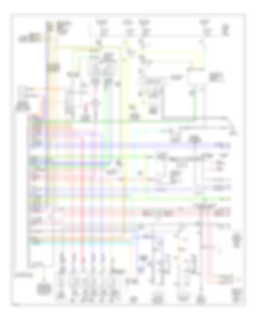
Transmission Wiring Diagram for Infiniti Q45 1995
List of elements for Transmission Wiring Diagram for Infiniti Q45 1995:
- (left kick panel)
- (right front of engine)
- 1-2
- 1st position switch
- A/t control unit
- A/t fluid temp. sensor
- All times
- Ascd control unit
- Automatic transaxle
- Battery
- Closed throttle
- Cruise control
- Cruise control system
- Data link connector (for consult) (in fuse block)
- Diagnostic information display control unit
- Dropping resistor (right front shock tower)
- Eccs control module (right kick panel)
- Eccs relay
- Electronic suspension (active susp control unit) (optional)
- Engine controls (maf sensor)
- Engine controls system
- Exterior lights (backup)
- Fuse 10a
- Fuse block (left kick panel)
- G119
- G200 (left i/p)
- Hot at
- Hot in on or acc
- Hot in on or start
- Inhibitor switch (side of transaxle)
- Instrument cluster
- Instrument cluster (tachometer)
- J/c
- Kickdown switch
- Line press. sol. valve
- Nca
- Over- run clutch sol. valve
- Pnk
- Red
- Resistor
- Revolution sensor
- Sensor
- Shift sol. valve a
- Shift sol. valve b
- Speedometer
- Tcc sol. valve
- Throttle position sensor (on throttle body)
- Throttle position switch (on throttle body)
- Turbine revolution
- Vehicle speed sensor
- Wot
 English