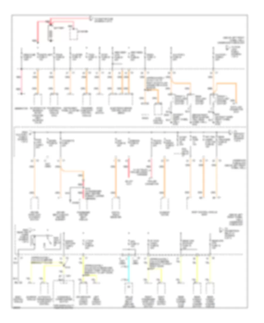
БЛОК ПРЕДОХРАНИТЕЛЕЙ И РЕЛЕ
Электросхема блока предохранителей и реле (1 из 4) для Hummer H3 2007
Электросхема блока предохранителей и реле (1 из 4) для Hummer H3 2007 - Список элементов:
- (above left front wheel well) underhood fuse block
- (approximately 2 cm (0.8 in) before breakout to c125)
- (approximately 24.5 cm (9.6 in) rearward of body pass through in breakout to left door) s264
- (behind right rear quarter trim, near wheel well) g340
- (not used)
- (on right inner front wheel well) g106
- Abs/vses1 -mtr fuse 67 40a
- Abs/vses2 -sol fuse 64 30a
- Amp fuse 38 25a
- Automatic transmission floor shift control
- Aux pwr 1 fuse 51 20a
- Aux pwr 2 fuse 45 20a
- Battery
- Bcm fuse 10a
- Body control module
- Body control module (bcm)
- C201
- Cluster fuse 19 10a
- Cnstr vent fuse 31 10a
- Data link connector (dlc)
- Digital radio receiver
- Diode
- Driver door lock & window switch
- Driver seat cushion heater element
- E-brake fuse 83 30a
- Electronic brake control module (ebcm)
- Evaporative emission (evap) canister vent solenoid valve
- From b aux pwr 1 fuse 51 (diagram 1 of 4)
- From c rear trn/ hazrd fuse 20 (diagram 1 of 4)
- Front 1 auxiliary power outlet
- Front 2 auxiliary power outlet
- Front passenger door lock & window switch
- Frt trn/ hazrd/ ctsy mir fuse 56 15a
- Generator
- Grille lamps relay (dealer installed)
- Htd/seats fuse 1 20a
- Hvac control module
- Instrument panel cluster (ipc)
- Left rear window switch
- Lt pwr wndw fuse 68 30a
- Mega fuse fuse 91 125a
- Nca
- Passenger heated seat module
- Pcm cntrl relay
- Pcm-b fuse 25 10a
- Powertrain control module (pcm)
- Pwr s/roof fuse 57 30a
- Pwr/ lock fuse 8 20a
- Radio
- Radio fuse 13 10a
- Rap/ accy relay
- Rear auxiliary power outlet
- Rear trn/hazrd fuse 20 20a
- Rear window washer fluid pump
- Rear window wiper/ washer module
- Rear window wiper/ washer switch
- Rear wpr sw/pump fuse 16 15a
- Rear/wpr mtr fuse 15 15a
- Red
- Right rear window switch
- Rt pwr wndw fuse 63 30a
- S/roof frt/wpr fuse 9 15a
- S143
- S205
- S319 (in passenger seat heater element jumper harness)
- Sdars fuse 50 10a
- Spo fuse 10 10a
- Start fuse 30a
- Starter
- Stop fuse 54 15a
- Stop lamp switch
- Sunroof module
- Sunroof motor
- Tccm fuse 12 30a
- To onstar fuse (diagram 4 of 4)
- To powertrain relay 81 (diagram 2 of 4)
- To pwr/ lock fuse 8 (diagram 1 of 4)
- To rap/accy relay 88 (diagram 1 of 4)
- Trailer connector
- Transfer case shift control module
- Trlr b+ fuse 84 30a
- Turn signal/multi- function switch
- Underhood fuse block (above left front wheel well)
- W/ hd truck trailer wiring harness
- Windshield wiper/washer switch
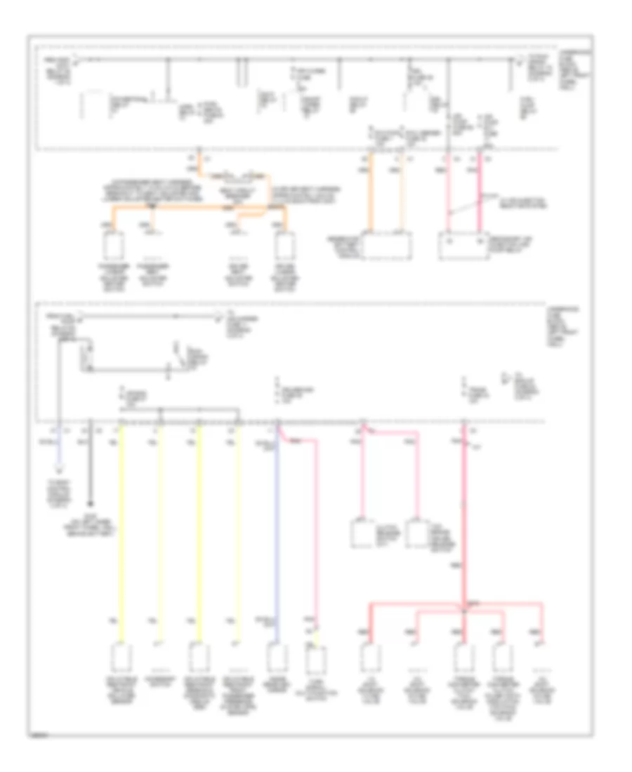
Электросхема блока предохранителей и реле (2 из 4) для Hummer H3 2007
Электросхема блока предохранителей и реле (2 из 4) для Hummer H3 2007 - Список элементов:
- (in driver seat harness, approximately 28.5 cm (11.2 in) back from c307) s312
- (in passenger seat harness, approximately 10 cm (3.9 in) before breakout to seat adjuster and lumbar adjuster/heater switches) s341
- 1-2 shift solenoid (1-2 ss) valve
- 2-3 shift solenoid (2-3 ss) valve
- 3-2 shift solenoid (3-2 ss) valve
- A/t
- Accessory switch
- Air bag fuse 27 10a
- Air pump fuse 62 60a
- Air pump rly fuse 60a
- Clutch release switch (m/t)
- Cruise/misc fuse 35 10a
- Driver lumbar adjuster/ heater switch
- Driver seat adjuster switch
- Drl fuse 39 10a
- Drl relay
- Fog/lp relay
- From fuel/ e pump relay 66 (diagram 2 of 4)
- From rap/ d accy relay 88 (diagram 1 of 4)
- Frt/wiper fuse 25a
- Fuel/ pump relay
- G105 (on left inner front wheel well, behind battery)
- Generator battery control module
- Hdlp relay
- Horn relay
- Inflatable restraint front passenger presence system (pps) sensor
- Inflatable restraint sensing & diagnostic module (sdm)
- Inflatable restraint vehicle rollover sensor
- Inside rearview mirror
- On/off wiper relay
- Passenger lumbar adjuster/ heater switch
- Passenger seat adjuster switch
- Pnk
- Powertrain relay
- Pwr/ seats fuse 61 40a
- Red
- Run/ crank relay
- Rvc pwr fuse 7 10a
- Rvc vsense+ fuse 32 10a
- S133
- Seat circuit breaker 20a
- Secondary air injection (air) pump relay
- Tcc brake/ cruise release switch
- To air cmprsr fuse 11 (diagram 3 of 4)
- To bak/up fuse 28 (diagram 3 of 4)
- To body control module (diagram 4 of 4)
- To run/ crank relay 78 (diagram 2 of 4)
- Torque converter clutch (tcc) solenoid valve
- Torque converter clutch pulse width modulation (tcc pwm) solenoid valve
- Trans fuse 34 10a
- Turn signal/ multi-function switch
- Underhood fuse block (above left front wheel well)
- W/ air injection reactor system
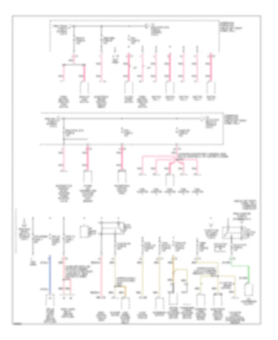
Электросхема блока предохранителей и реле (3 из 4) для Hummer H3 2007
Электросхема блока предохранителей и реле (3 из 4) для Hummer H3 2007 - Список элементов:
- (above left front wheel well) underhood fuse block
- (approximately 15 cm (6 in) from c203) s220
- (approximately 5 cm (0.2 in) before breakout to ebcm) s141
- (in dealer installed off road harness, 1.5 cm (5.9 in) from roof lamps relay, near master cylinder) s101
- (in engine compartment harness, near grille lamps relay, by master cylinder) s103
- (not used)
- A/c clutch diode 90
- A/c clutch fuse 48 10a
- A/c clutch relay
- A/c compressor clutch
- A/t
- A26
- Abs/vses fuse 29 10a
- Accessory switch
- Air cmprsr fuse 11 25a
- Back-up lamp switch
- Bak/up fuse 28 15a
- Blower motor
- Body control module (bcm)
- Clutch start switch
- Driver lumbar adjuster/ heater switch
- Electronic brake control module (ebcm)
- Eng cntrl sys fuse 22 15a
- Evaporative emission (evap) canister purge solenoid valve
- From ign 1 i fuse 33 (diagram 3 of 4)
- From injector fuse 23 (diagram 3 of 4)
- From run/ crank relay 78 (diagram 2 of 4)
- From trans f fuse 34 (diagram 2 of 4)
- Fuel injector
- Grille guard fuse 2 20a
- Grille guard lamps relay (dealer installed)
- High speed blower motor relay
- Hvac blwr fuse 82 30a
- Hvac cntrl hd fuse 59 10a
- Hvac control module
- Hvac relay
- Ign 1 fuse 33 15a
- Ignition coil 1
- Ignition coil 2
- Ignition coil 3
- Ignition coil 4
- Ignition coil 5
- Injector fuse 23 15a
- Intake air temperature (iat)/mass air flow (maf) sensor
- M/t
- Nca
- Park/ neutral position (pnp) switch
- Passenger lumbar adjuster/ heater switch
- Pcm i fuse 21 10a
- Pnk
- Powertrain control module (pcm)
- Pwr htr switch fuse 53 10a
- Red
- Roof lamps relay (dealer installed)
- Roof lp fuse 4 20a
- Rr defor relay
- Steering wheel position sensor (swps)
- Tccm switch fuse 58 10a
- To a/c clutch relay 76 (diagram 3 of 4)
- To batt ign sw fuse 5 (diagram 4 of 4)
- To eng cntrl sys fuse 22 (diagram 3 of 4)
- Underhood fuse block (above left front wheel well)
- Vses/ abs fuse 52 10a
- W/ active brake control
- Yaw rate/ lateral & longitudinal accelerometer sensor
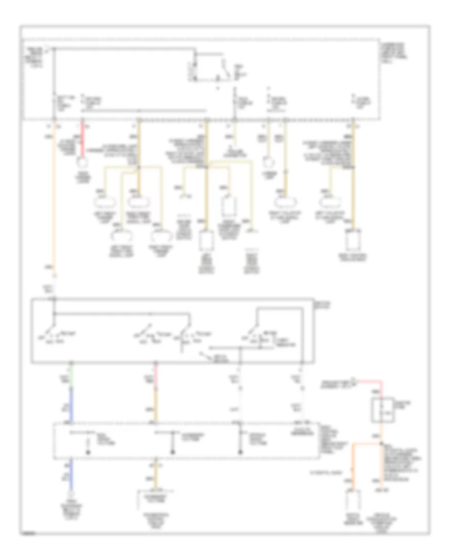
Электросхема блока предохранителей и реле (4 из 4) для Hummer H3 2007
Электросхема блока предохранителей и реле (4 из 4) для Hummer H3 2007 - Список элементов:
- (in body harness under left door sill plate, approximately 41 cm (16.1 in) rearward of body pass through in main bundle) s309
- (in body harness, approximately 6 cm (2.4 in) to right of stop lamp switch breakout in main harness) s209
- (in forward lamp harness, approximately 43 cm (17 in) from c115) s109
- 10a
- 5-volts reference
- A14
- A48
- Acc
- Accessory voltage
- Batt ign sw fuse 5 10a
- Body control module (bcm)
- Body control module (bcm) (behind right front kick panel)
- C1 b7
- C2 a42
- Digital radio receiver
- Driver door lock & window switch
- From battery a (diagram 1 of 4)
- From rr k defor relay 71 (diagram 3 of 4)
- From run/crank relay 78 (diagram 2 of 4)
- Front passenger door lock & window switch
- Frt/prk fuse 43 10a
- Ignition switch
- Key-in switch
- Left front marker lamp
- Left front park/turn signal lamp
- Left rear door window switch
- Left tail/stop & turn signal lamp
- License lamp
- Lr prk fuse 37 10a
- Off
- Off/run/ crank voltage
- Onstar fuse
- Powertrain control module (pcm)
- Prk/ lp relay
- Red
- Right front marker lamp
- Right front park/turn signal lamp
- Right rear door window switch
- Right tail/stop & turn signal lamp
- Roof marker lamps
- Rr prk fuse 49 10a
- Run
- Run/ crank voltage
- S234 (w/ digital audio) (in i/p harness center dash area, approximately 5 cm (2 in) left of breakouts to hvac in main bundle)
- Start
- Theft resistor
- Trailer connector
- Trlr fuse 55 10a
- Underhood fuse block (above left front wheel well)
- Vehicle communication interface module (vcim)
- W/ digital audio
- W/ roof mounted marker lamps

 Čeština
 Dansk
Dansk Deutsch
 Ελληνικά
 English
 Español
 Suomi
Suomi Français
 Français
 עברית
עברית Hrvatski
 Magyar
 Italiano
 日本語
日本語 한국어
한국어 Nederlands
 Polski
 Português
 Português
 Română
 Русский
 Slovenčina
 Slovenščina
 Svenska
 Türkçe
 中文 (中国)