СИСТЕМА ПЕРЕДАЧИ ДАННЫХ
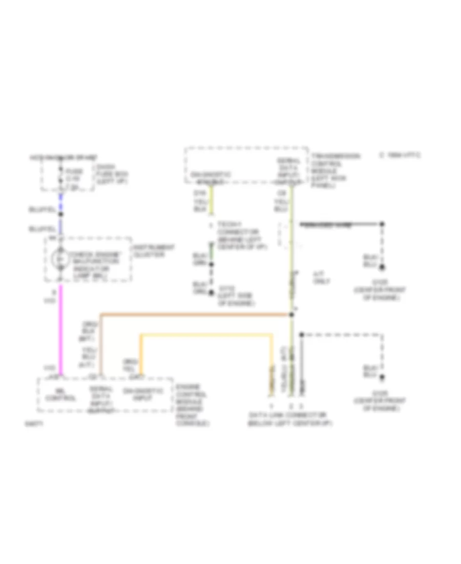
схема соединителя канала связи для Isuzu Trooper RS 1994
схема соединителя канала связи для Isuzu Trooper RS 1994 - Список элементов:
 English
схема соединителя канала связи для Isuzu Trooper RS 1994
схема соединителя канала связи для Isuzu Trooper RS 1994 - Список элементов: