СИСТЕМА УПРАВЛЕНИЯ ДВИГАТЕЛЯ
4.1L
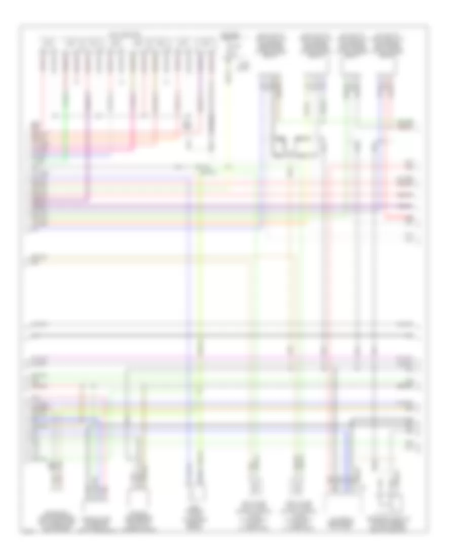
4.1L, Электросхема системы управления двигателя (1 из 4) для Infiniti Q45 t 2001

4.1L, Электросхема системы управления двигателя (1 из 4) для Infiniti Q45 t 2001 - Список элементов:
- (30-33 not used)
- (37-40 not used)
- (front of right front fender)
- (on left front side of eng, forward of left throttle body) iacv-aac valve
- Air conditioning system
- Check connector (in right rear of eng compt)
- Cooling fans system
- Eccs control module (ecm) (behind right kick panel)
- Evap canister purge control solenoid valve (on top right rear of eng)
- Evap canister purge volume control solenoid valve (on top right rear of eng)
- Evap canister vent control valve (under right rear of vehicle, on evap canister)
- G101
- Iacv-ficd solenoid valve (left front side of eng compt, forward of throttle body)
- Ignition coils
- Instrument cluster system
- Map/baro switch solenoid valve (on top center rear of eng)
- Pnk
- Power steering oil pressure switch (on power steering high pressure tube)
- Red
- Resistor (behind right kick panel)
- Vacuum cut valve bypass valve (under right rear of vehicle, forward of evap canister)
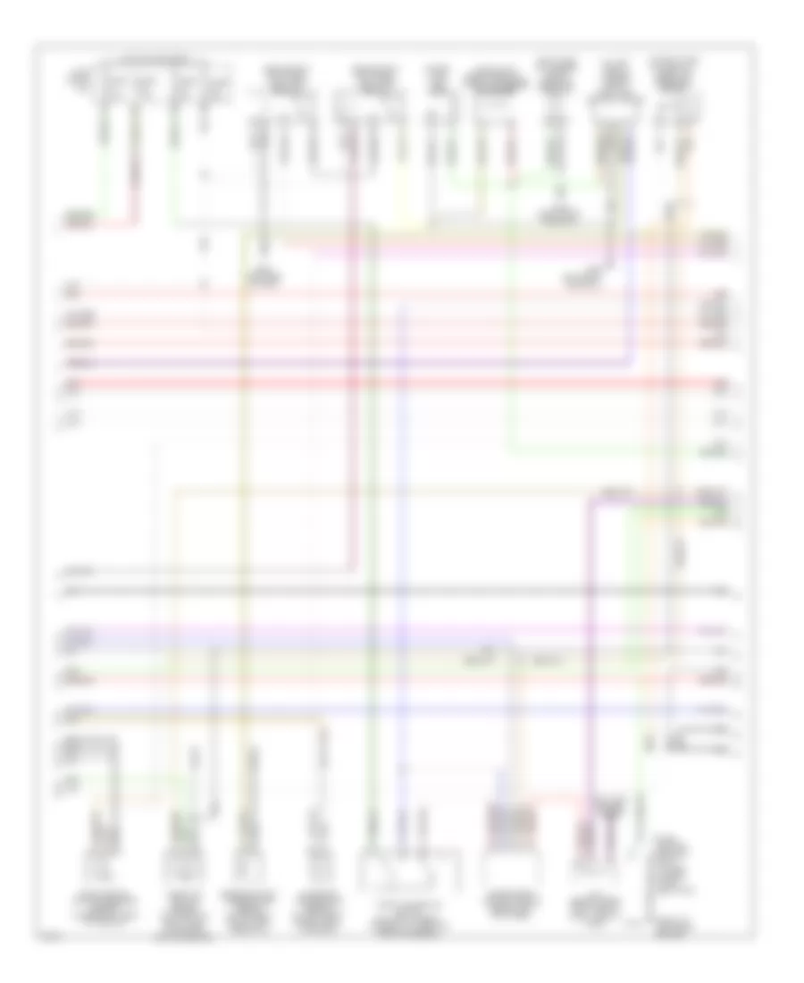
4.1L, Электросхема системы управления двигателя (2 из 4) для Infiniti Q45 t 2001
4.1L, Электросхема системы управления двигателя (2 из 4) для Infiniti Q45 t 2001 - Список элементов:
- tac module (behind right kick panel)
- (on inlet of left catalytic converter) front heated oxygen sensor (bank 1)
- (on inlet of right catalytic converter) front heated oxygen sensor (bank 2)
- (on outlet of left catalytic converter) rear heated oxygen sensor (bank 1)
- (on outlet of right catalytic converter) rear heated oxygen sensor (bank 2)
- Camshaft posi- tion sensor (on front of left cylinder head)
- Crankshaft position sensor (bottom right side of transmission bellhousing)
- Egrc solenoid valve (top center rear of engine)
- F75
- Fuel injectors
- Fuse 10a
- Fuse block
- Hot in on or start
- Left intake valve timing control solenoid valve (on top front of left cylinder head)
- Mass air- flow sensor (between air duct & air cleaner housing)
- Nca
- Pnk
- Red
- Right intake valve timing control solenoid valve (on top front of right cylinder head)
- Secondary throttle position sensor (on throttle body, next to air duct)
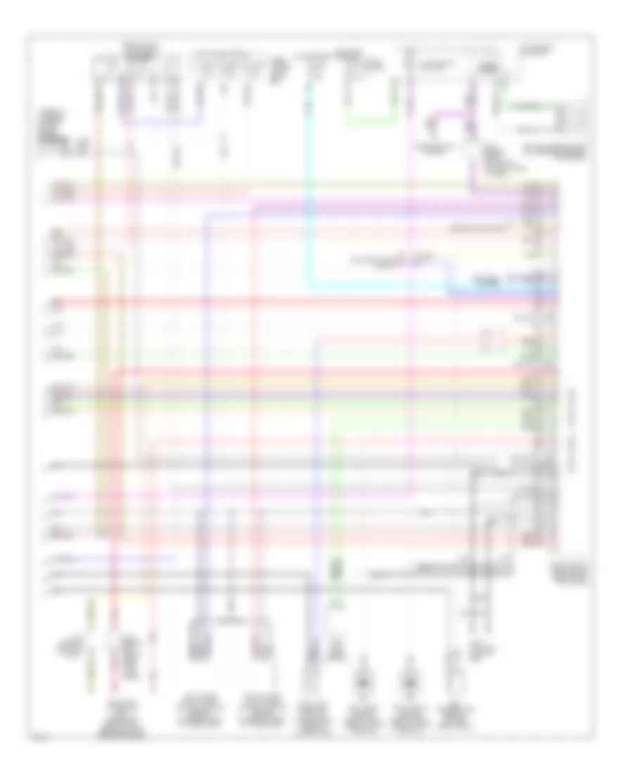
4.1L, Электросхема системы управления двигателя (3 из 4) для Infiniti Q45 t 2001
4.1L, Электросхема системы управления двигателя (3 из 4) для Infiniti Q45 t 2001 - Список элементов:
- (above left rear wheelwell, taped to harness) condenser
- (behind right kick panel) fuel pump relay-1
- (behind right kick panel) fuel pump relay-2
- (front of left front fender)
- (in fuel tank) fuel pump
- (on left side of luggage compt) fuel pump control module
- (on right side of firewall) absolute pressure sensor
- (right side of luggage compt) dropping resistor
- 12g
- 15b
- Anti-lock brakes system
- Engine coolant temperature sensor (on top right fonr of eng, near inj 2)
- Evap control system pressure sensor (under right rear of vehicle)
- Fuse 10a
- Fuse 15a
- Fuse 7.5a
- Fuse block (j/b)
- G100
- G202 (left side of dash)
- G309 (left front door sill)
- G316 (right front door sill)
- Hot in on or start
- Intake air temperature sensor (on left front of eng compt, in air duct)
- J/c 6 (behind upper right side of dash, tape to harn)
- Nca
- Park/ neutral position relay (in fuse, fusible link & relay box)
- Red
- Throttle position sensor (on throttle body, near intake mani- fold collector)
- Throttle position switch (on throttle body, integral to throttle position sensor)
- Transmission control module (behind left kick panel)
4.1L, Электросхема системы управления двигателя (4 из 4) для Infiniti Q45 t 2001
4.1L, Электросхема системы управления двигателя (4 из 4) для Infiniti Q45 t 2001 - Список элементов:
- (104 not used)
- (107 not used)
- (109-120 not used)
- (84-88 not used)
- (94-95 not used)
- (behind right kick panel) eccs relay
- (taped to harness, on right side of engine) condenser
- Air conditioning system
- Data link connector (dlc) (under left side of dash, near hood lock release handle)
- Defogger system
- Eccs control module (ecm) (behind right kick panel)
- Egr temperature sensor (top left rear of eng)
- Fuel tank gauge unit (tank fuel temperature sensor) (in fuel tank)
- Fuse 10a
- Fuse 15a
- Fuse 7.5a
- Fuse block
- Fuse, fusible link & relay box
- G110 (top left front of eng)
- Headlights system
- Hot at all times
- Hot in on or start
- Hot in start
- Instrument cluster
- J/c 2 (behind left side of dash, near fuse block)
- J/c 6 (behind upper right side of dash, taped to harn)
- J/c 8 (behind left kick panel)
- Left intake valve timing control position sensor (on rear of left cylinder head)
- Left knock sensor (below left side of intake manifold)
- Malfunction ind lamp
- Nats immu (near ashtray)
- Nca
- Pnk
- Red
- Right intake valve timing control position sensor (on rear of right cylinder head)
- Right knock sensor (below right side of intake manifold)
- Speedo- meter
- Transmissions system
- Vehicle speed sensor (on transmission rear extension)