AIR CONDITIONING
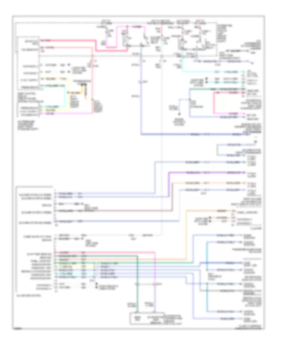
Manual A/C Wiring Diagram for Dodge Dakota 2010
List of elements for Manual A/C Wiring Diagram for Dodge Dakota 2010:
- (a/c compressor) a/c compressor clutch
- 87a
- A/c clutch relay
- A/c clutch rly ctrl
- A/c heater control
- A/c pressure transducer (right front of engine compt)
- Blend door drv
- Blower
- Blower motor (front of hvac unit)
- Blower motor high speed
- Blower motor low speed
- Blower motor m1 speed
- Blower motor m2 speed
- C100
- C121
- C13
- C18
- C201
- C201 c
- C21
- C210
- C29
- C32
- C34
- C61
- C71
- C72
- C73
- C75
- C801
- Can b bus (+)
- Can b bus (-)
- Can c (+)
- Can c (-)
- Cluster
- Common door drv
- Computer data lines system
- D54
- D55
- D64
- D65
- Door drv
- Driver blend door actuator
- E12
- Ect sig
- Engine controls system
- Engine coolant temperature sensor (right front side of engine)
- Evap temp sens sig
- Evaporator temp sens sig
- Evaporator temperature sensor (on hvac unit)
- F504
- Fcm sens rtn
- Floor to defrost mode door actuator
- Front blower motor resistor (right side of hvac unit)
- Front control module (side of power distribution module)
- Ft blw hi spd
- Ft blw lo spd
- Ft blw m1 spd
- Ft blw m2 spd
- Fuse 10a
- Fuse 11 10a
- Fuse 40a
- Fuse 7 10a
- Fused ign sw out (run)
- G107 (right side of engine compt)
- G200 (left side of dash)
- G201 (right side of dash)
- Gnd
- Ground
- Hot at all times
- Hot in run or start
- Hot w/ ignition run relay energized
- Ign sw out (run)
- Integrated power module (left side of engine compt)
- Ipm
- K900
- Mode door 1 drv
- Mode door 2 drv
- Motor relay
- Panel lamps drv
- Passenger blend door actuator
- Pnk
- Powertrain control module (right side of engine compt)
- Pressure sig
- Recirculation
- Recirculation door actuator (right side of hvac unit)
- Recirculation door drv
- Red
- S114 (right side of engine compt)
- S115 (right side of engine compt)
- S123 (top of engine)
- S217 (center of hvac)
- Sens gnd
- T103
- Transmissions system
- Z24
- Z961
 English